In my recent post on the Leg and Hip Prototype, I wasn’t happy with how the motor control was behaving.
It was too inconsistent, and jerky.
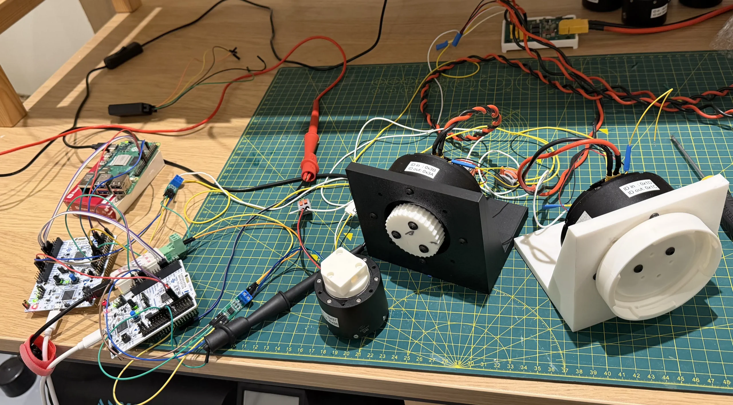
I decided recreating the bilateral telepresence setup I saw on Josh Pieper’s and Skyentific’s Youtube channels.
How it works

After experimenting in position control, I realised I needed to ditch that and implement torque control.
To calculate the torque I needed to know:
- Position of motor A
- Position of motor B
- Speed of motor A
- Speed of motor B
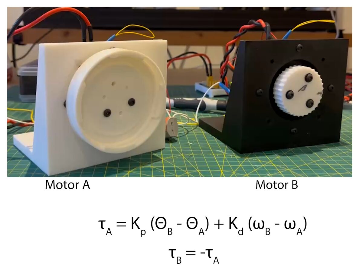
These are then applied with two constants, Kp and Kd, to determine the needed torque as:
Torque_motorA = Kp * (Position_motorB - Position_motorA) + Kd * (Speed_motorB - Speed_motorA);
Torque_motorB = -Torque_motorA;
Kp in this effectively acts like a spring constant, and Kd as a damping constant.
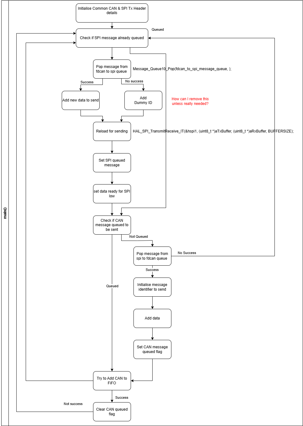
The software then loops getting the positions and speeds, calculating torques, and commanding torques.
Positions, speeds are used from motor’s response to the torque command.
Changing the values of Kp and Kd allow the feel and behaviour of the physical system to be adjusted.
Issues along the way
In the SteadyWin protocol, there are a couple of ways to get position and speed information from the motor.
The first way is through the “Retrieve Indicator” command, and requesting either output shaft angle or speed which provides data for a 32bit float.
The second way is through the motor’s response to a control command (any of position, torque or speed). As part of the response it sends temperature, position, speed and torque.
The position value is 16 bit which gets converted to a float through a provided formula.
The speed and torque values are 12bits which also get converted to floats through their own formulas.
I requested some more info on the difference between these values (also if the torque was the same as the retrieve indicator q-current multiplied by the motor’s torque constant), but have not had any feedback yet.
As I was playing around with these and upgrading the motor visualiser I was able to determine the following:
- Retrieve indicator for output shaft speed does not give a usable value (basically ±0)
- The two position values differ slightly, for one motor I saw ~+0.02° to ~-0.35° in difference.
The difference in position value was unnoticeable on the graph when the motors were moving.
Something to keep in mind for the future and may need to be accounted for in calibration by adjusting the position formula if the 16bit value is sufficient.
This also casts some doubt over the accuracy of the other received values for speed and torque.
The demo was quite easy to get into an oscillating state with the two motors being out of phase with each other. I could do this by putting the Kp value a few times bigger than the Kd value.
I expect this is due to the rate I’m running the loop at, ~100Hz.
Making some changes to the code to make the loop run on the back of a timer interrupt, and at a desired frequency, I was able to confirm the loop rate was having an impact on the oscillations. Running at 500Hz, the oscillations didn’t appear until much larger values of Kp and Kd, and at a different frequency. I also noticed that during this, the torques were hitting my arbitrary 10Nm torque limit which could be stopping it from further increasing, it continued to happen when I bumped the torque limits up to 20Nm.
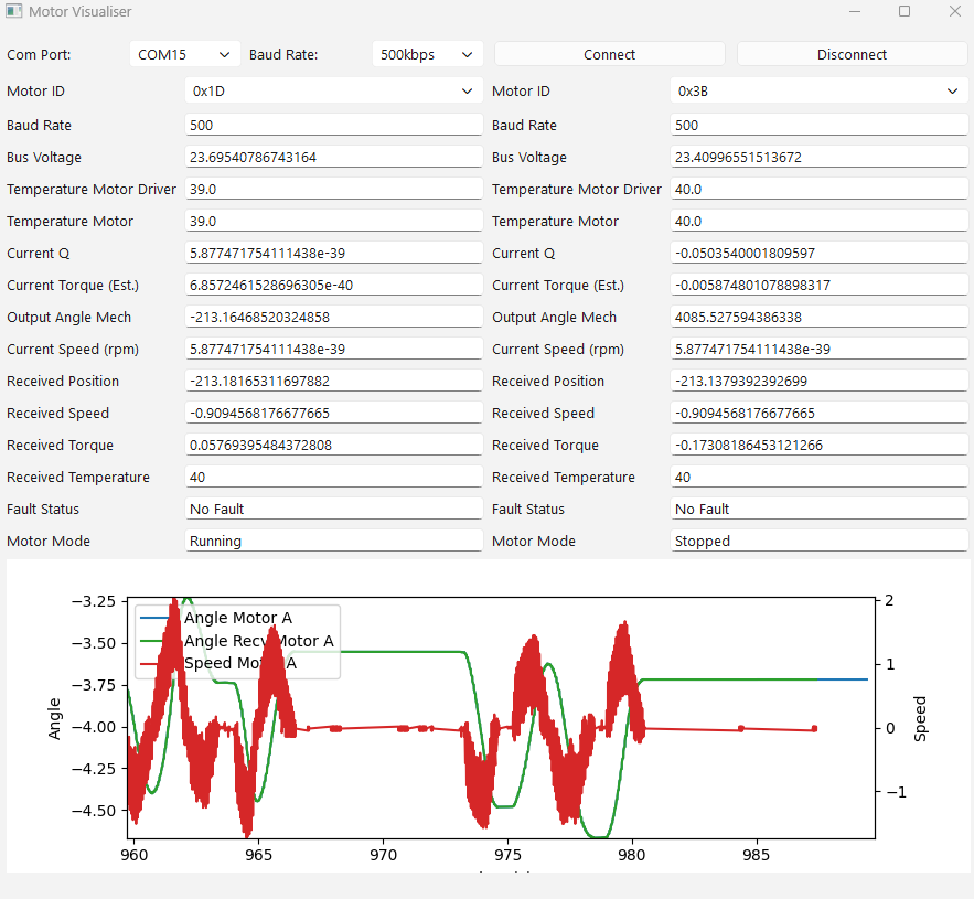
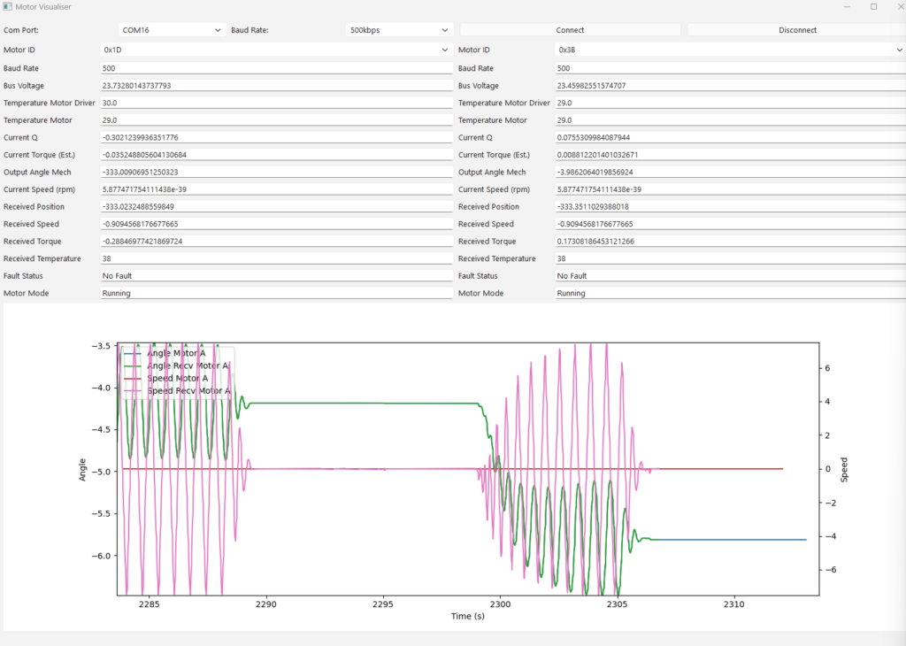
Image showing the oscillating impact on speed (red) at loop speed of 500Hz.
Upgrades to the Motor Visualiser
Working through the demo, I was continuously trying to add more to the motor visualiser to help with my root cause analysis.
Initially I tied Retrieve indicator position and received position values together but split these after seeing the difference. It would be nice to merge these if the difference can be resolved through calibration.
A torque estimate and speed field was added, which helped highlight no speed info was coming through.
The biggest change was the addition to the graph.
Although limited in function now, it gives a clear view of what the system is doing at the time and the prior 30 seconds.
The image shows the constant speed value in red, oscillations in speed in pink, and the position in green and blue from the two different retrieval methods.
I want to use the STM32 G4 as the MCU for the control board. I’ve now ported the telepresence program from the F4 Disco to a Nucleo-G474, and started work towards the control board.