Why?
Up until now, the motor control has been either direct from the PC through a USB to CAN device, or running on an STM development board.
Both are a few steps away from what the actual implementation form will be.
I wanted to close this gap by incorporating the Raspberry Pi coupled with an MCU.
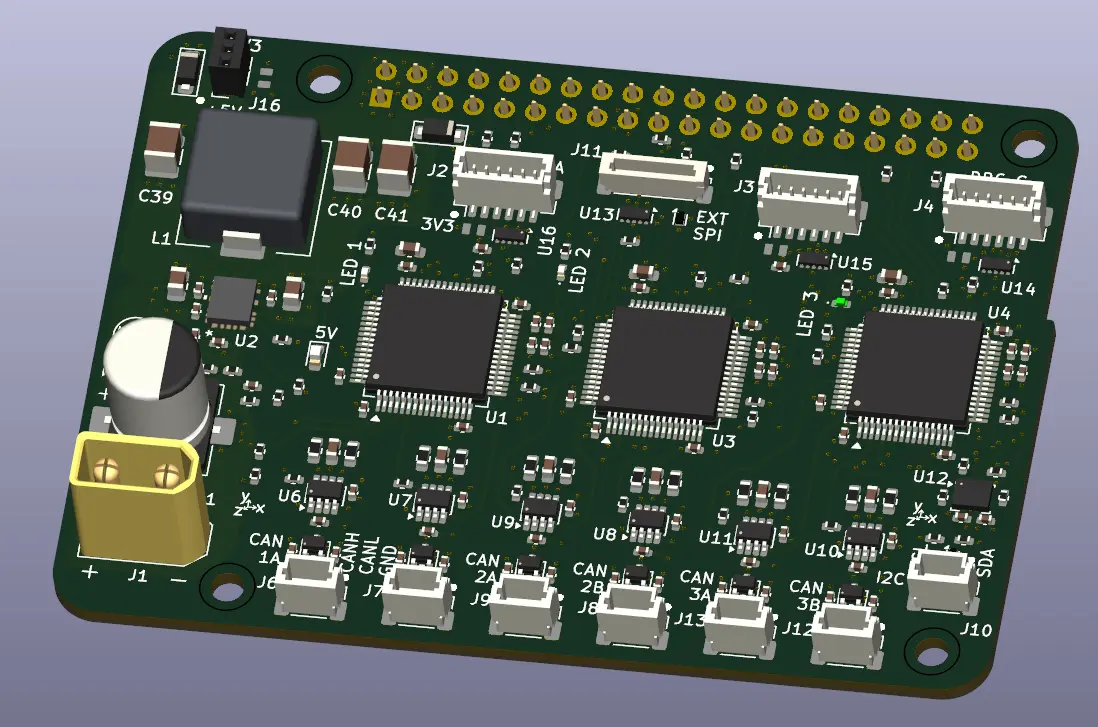
It has also been some time since I’ve created a PCBA with MCUs. I thought it would be worthwhile spending some time working through some code for the MCU to further flesh out the details of what I need to incorporate into the communication (comms) board.
What?
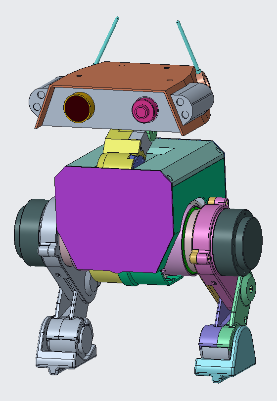
The plan is to have the comms board in the form of a Pi hat. The Pi does the control and heavy lifting while the MCUs provide the interface to the other devices. For now the devices are primarily the nine SteadyWin motors, but I also need to fold in interfacing with the servos for the head and any other auxiliary features; speakers, and lights etc.
How
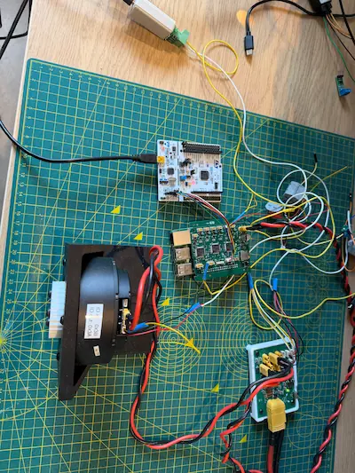
I had already purchased a few STM32G4 Nucleo boards previously and had a Raspberry Pi on hand.
It was a matter of connecting these two together, and writing software for the Pi and Nucleo.
The Nucleo software was basically completely reset, all of the SteadyWin module being redundant beyond the learnings being passed to the implementation on the Pi.
The Pi software was able to leverage some of the early python modules I made when controlling the motors directly. With some updates taken from the C implementation and all the development trials I’d done since.
Hardware Architecture
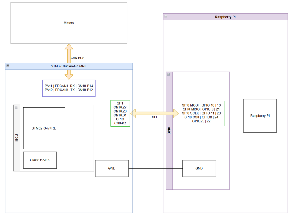
The CAN interface was kept the same as previous testing. Using the TJA1050 modules between the Nucleo and the CAN bus.
The new addition was adding in the SPI. I used SPI0 on the Pi side and SPI1 on the Nucleo (SPI2 and SPI3 are shared with the I2S2 and 3).
On the CAN bus I kept the two motors I’d been using in the telepresence demos.
Software Architecture
The goal to test the system was to reimplement the telepresence demo that I’d run purely from the Nucleo.
This meant I needed:
- Control and motor instances reflected on the Pi
- A message relay between Pi and CAN transceiver on the Nucleo
Raspberry Pi
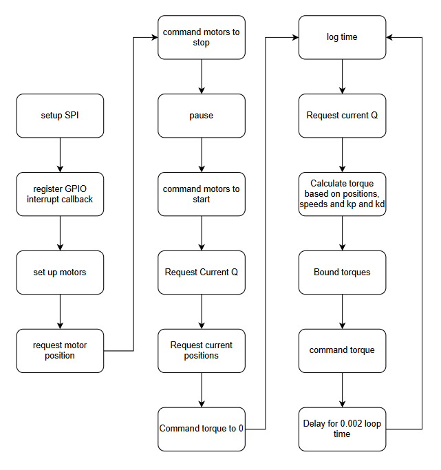
The Pi program simply implements the control loop previously set up on the Nucleo telepresence demo.
The differences are that it uses spidev to send SPI messages to the Nucleo and lgpio to read the data ready flag coming from the Nucleo.
Nucleo
The Nucleo system resolves around two Single Producer Single Consumer (SPSC) message queues.
One going from SPI to CAN, the other from CAN to SPI
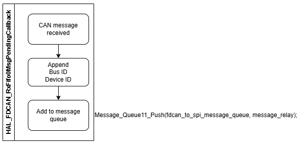
Interrupt Callbacks
When the CAN received callback is triggered, it takes the received 8 byte message, prepends the device ID (retrieved from the CAN message header), and a bus ID (to be unique per MCU). The prepended message is the added to the message queue.
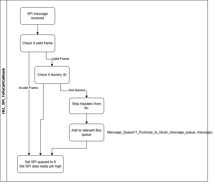
When the SPI received callback is triggered the message goes through some additional steps.
First, the header and tail is checked to be valid (one 0xAA byte at the start and a 0x55 byte at the end), if invalid the message is discarded.
Second, the device ID is checked. If the device ID is 0x00 (that is a dummy ID), the message is also discarded.
The dummy ID is used when only one side of the pi or Nucleo needs to send a message and the other has no data.
A dummy ID is used by the transmitter side so the receiver knows to discard it on reception.
Third, the message is added to the message queue going to the CAN bus.
Once these have been completed the flag for SPI being queued ready and the GPIO data ready signal being set to the pi are set to False.
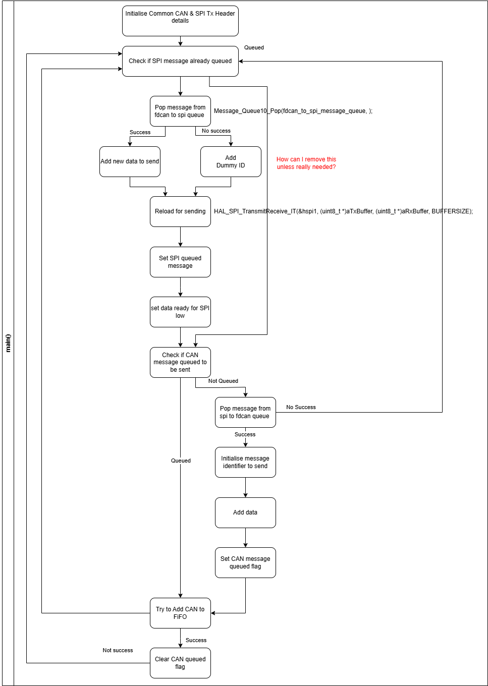
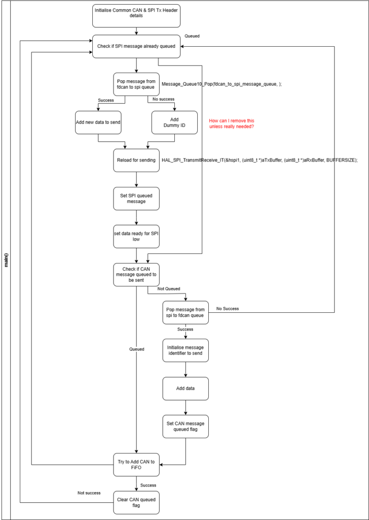
Main Loop
The job of the main loop is to continuously reload the SPI and CAN buses with new messages from the message queues.
As the SPI is responding to a master device (the Pi), it also needs to reload the SPI when no messages are available to account for transmissions from the Pi prior to new messages being available (in this case from CAN responses).
The first is if a SPI message is not queued. Trying to pop a message from the fdcan to spi queue is successful/True if there’s a message to retrieve, and False if it’s empty. This allows splitting into adding legitimate data or a dummy ID for the master to receive and ignore. It would be nice to be able to wait for actual data and avoid loading the dummy but the Pi will likely initiate a new SPI transfer prior to that.
The message is then loaded to the SPI, with necessary flags and GPIOs being set/reset as needed.
The second half is the CAN preparing. The primary difference is that it doesn’t need a dummy message. If the message queue is empty, i.e. pop returns false, the program simply returns to the start of the loop with the SPI loading. The other difference is loading to the CAN bus. The STM32G4 uses a FIFO for loading the CAN with 3 slots. Prior to attempting to add, the program checks if it’s full, and adds if not. If it’s full, it holds on to the prepared message and rechecks in the next iteration. This behaviour does mean the flags are subtly different between SPI and CAN, with CAN the queued flag signals the message is ready to add the FIFO (and cleared once added), while the SPI queued flag is set once the SPI buffer is loaded and cleared once a SPI transaction has been completed.
Stumbling point along the way…
While updating the Nucleo code, I foolishly left in the timed loop in the main function. This meant I had a timed loop in the Pi code and in the Nucleo which lead to delays for control messages to propagate through from the Pi to the motors and back. Removing the Nucleo’s timed loop gave an instant boost in performance.
The other issue I had, was when the Pi had no message to send but the Nucleo did I set a GPIO pin as a flag to initiate a transfer. The implementation I created set a flag even when there was no real data to be sent back, just the dummy placeholder data. The result being a high volume of dummy messages firing back and forth with no real gain beyond the SPI buffers freeing and reloading. This situation isn’t an issue when the control is continuously sending messages but seemed like it should be preventable for the situations where it wasn’t. I fixed this in Prototype B.
Next
The next post will cover Prototype B which is to reflect multi MCUs, another step towards the real PCBA comms/CAN hat implementation.
I’ve also spent some time working on the reinforcement learning Isaac Lab program for the biped, which will be covered in an additional post.