Prototype B is intended to build off of Prototype A by adding another Nucleo and with it another CAN bus and motor to control.
The aim being to re-run the telepresence demo over the two buses.

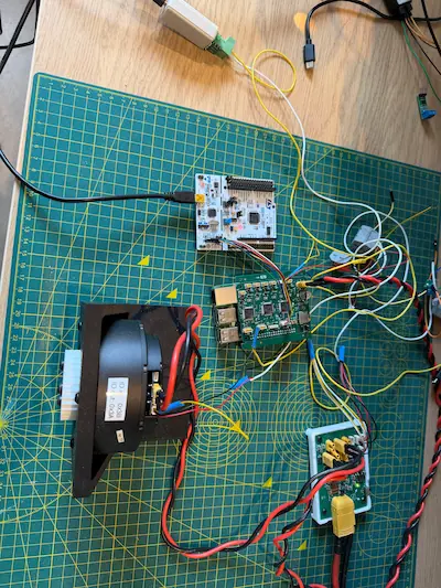
Hardware Architecture
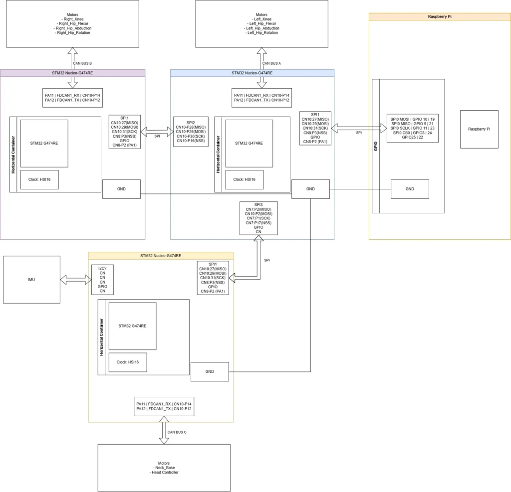
While it may look a bit more complicated than prototype A, there’s not too many significant hardware changes.
The blue and orange blocks are the same core Nucleo and Pi as in prototype A.
The purple and yellow Nucleos are the additions each interfacing with the blue Nucleo (Nucleo 0) with SPI.
The yellow Nucleo was never implemented as I don’t have a third STM32G474 Nucleo and it’s addition to the test would only be to stress test the system with the additional channels it opens. I opted to include it in the hardware and software block diagrams to ensure I could catch potential surprises prior to a PCBA sample spin up.
Nucleo 1 (purple) and 2 (yellow) take the Nucleo setup from prototype A, leveraging the same SPI and CAN ports and configuration. For Nucleo 2 I added a box for the IMU which is still undefined.
Nucleo 0 had the biggest changes with the addition of SPI2 and SPI3 usage. Configurations were mostly copied from SPI1 with the master parameters added on to this. The baud rate was dropped into the kHz range to minimise effect of traversing headers and jumpers.
Hardware NSS lines have been implemented (but may be removable with more testing) with additional GPIO lines from slaves to master to signal data ready.
Software Architecture
Raspberry Pi
The software flow followed the same as prototype A. The difference being in the motor details used, the bus ID and device ID.
I did have issues with motor starting errors which I tried to account for unsuccessfully, more in Challenges.
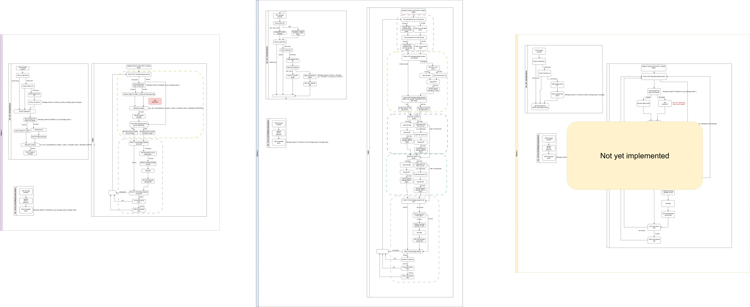
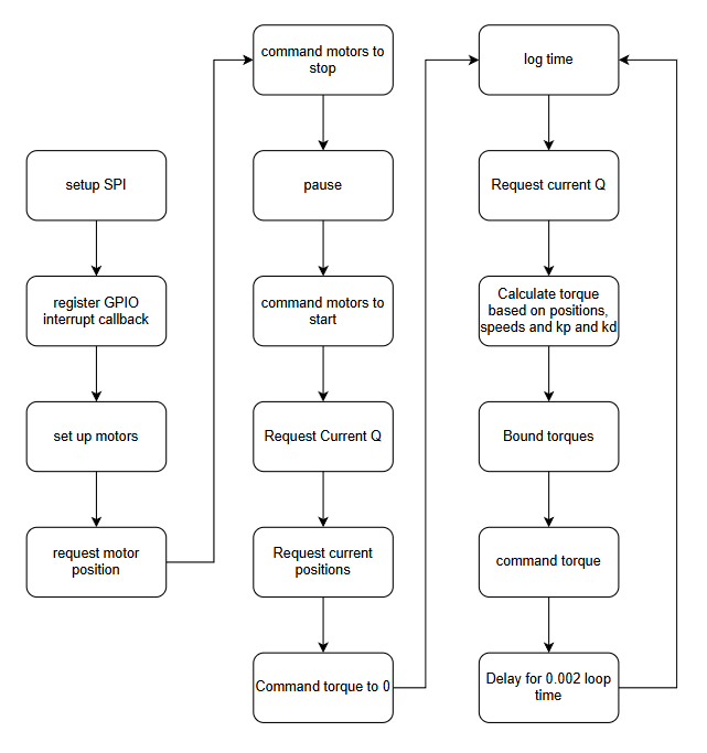
Nucleo 0 (Blue)
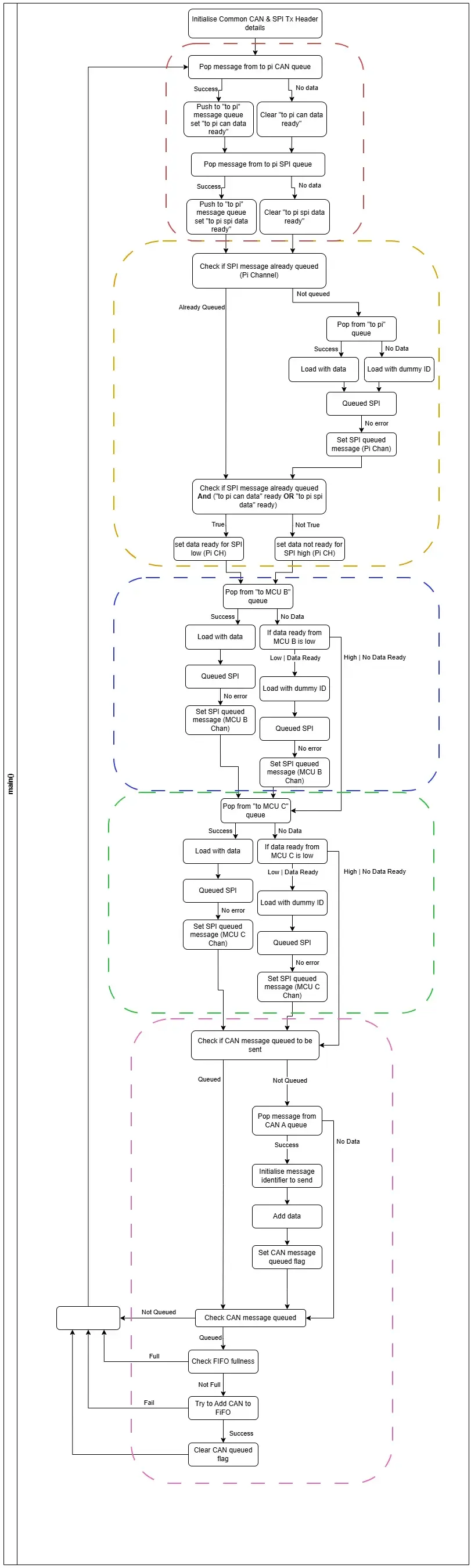
Whilst this flow is long, it can be broken into a few blocks with some small variations between.
The first, outlined in red, is responsible for taking messages in the “to pi CAN” and “to pi SPI” queues and merge it into one “to pi queue”.
As soon as data is not available from one, the relevant data ready flag is cleared.
The next 3 blocks, outlined in yellow, blue, and green, are for loading the relevant SPIs.
Yellow is responsible for SPI1, that is providing responses to the pi. If the SPI is not loaded it attempts to pop from the “to pi” queue, and proceeds to load the SPI with either data or a dummy message.
To avoid spamming of dummy messages back and forth, the SPI queued flag is used in conjunction with the data ready flags set in the red section (‘to pi can data ready’ and to pi spi data ready’). If queued and either data ready flag is set, the flag is sent to the master via GPIO. This means that if there’s no data coming through the queues, i.e. “no data ready”, the GPIO signal won’t be sent even once the SPI is queued with dummy data. If data does start coming through the queues then the flag gets raised and the SPI bus can restore sending messages.
The blue and green sections are the same, except targeting different MCUs and so different SPI channels. Blue is for Nucleo 1, and Green for Nucleo 2. As this device is the master, there’s no need to check if the SPI is queued as the queuing initiates the transfer. As long as the SPI has completed the prior transfer, it can reload the buffer with data and send.
If there’s no data to send to Nucleo 1 or 2, there’s no urgent need to load a dummy message as the slave can’t initiate the transfer. Instead, if not data is in the relevant to send queue the GPIO line is checked in case the slave has signalled it has data to send back. If the flag signals data ready, the SPI is loaded with a dummy message and a transfer initiated.
The final, pink, section is the CAN load and send. This is the same as in prototype A as covered previously so won’t be repeated.
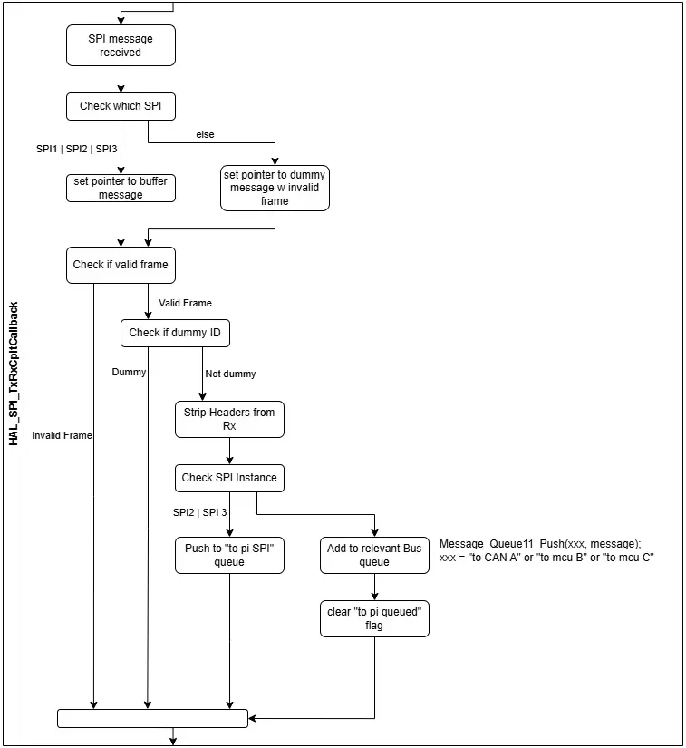
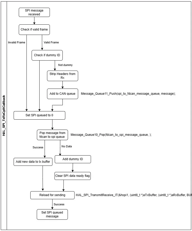
From prototype A, the SPI received interrupt handler has had to be expanded to account for the 3 SPI instances and the various message queues.
The checks for valid frame and dummy IDs is unchanged.
The important change is checking which instance triggered the interrupt, to allow reading of the right SPI receive buffer.
If the instance is from SPI2 or 3, the data is destined for the pi so gets pushed onto the ‘to pi SPI’ queue. Which gets consolidated into the ‘to pi’ queue at the start of main.
If the instance is from SPI1, the bus ID determines if it gets pushed onto the ‘to CAN A’, ‘to mcu B’, or the ‘to mcu C’ queue.
As data gets pushed onto the relevant queues, the respected data ready flags get set to true.
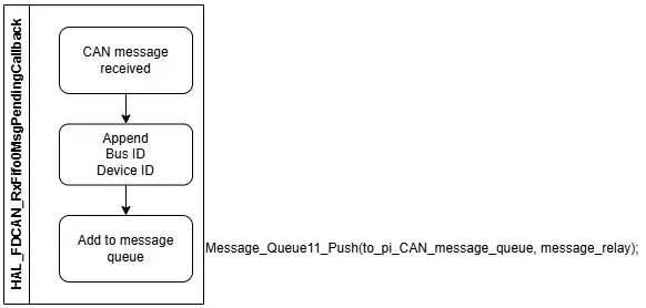
The CAN receive callback is unchanged from prototype A.
Nucleo 1 (Purple)/Nucleo 2 (Yellow)
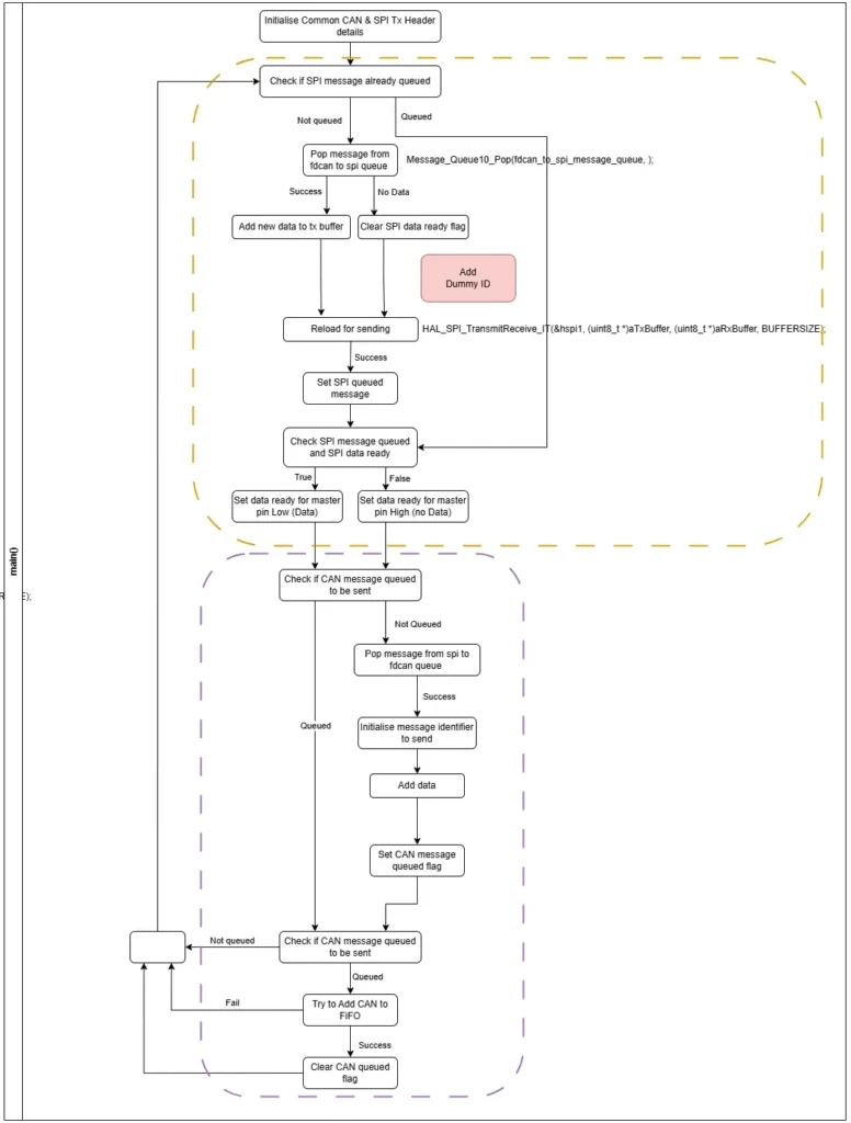

The Nucleo 1 uses a refined version of the prototype A code.
It reloads the SPI (yellow section) in a similar way to Nucleo0 does for the pi, including the data ready flag approach. A bug was incorporated in the main loop where the dummy ID wasn’t added which would need to get fixed. The SPI reload was also added to the SPI receive interrupt handler as well, this was a brute force way of ensuring data was ready for the next SPI transmission triggered by Nucleo 0. I had cases of mangled messages with the hypothesis being the slave SPI was not reloaded ready when the next transmission was initiated. This implementation included the correct loading of the dummy ID.
The CAN callback was again the same as in prototype A.
As there was no actual third Nucleo used, there’s no code for the Nucleo 2. However in regards to the prototype, it would be almost an exact copy of the Nucleo 1 code but use a different Bus ID when prepending the messages for sending back to the master MCU/Nucleo 0.
Challenges
As code was being modified in three places:
- Raspberry Pi
- Nucleo 0
- Nucleo 1
It made debugging more difficult and slower.
While the raspberry pi changes were small, the odd typo did slip in.
To debug Nucleo 0 and 1, I initially would set one in release configuration and use the other in debug mode with STM32CubeIDE. This was largely effective but I did encounter cases where it was hard to know where the fault was. Placing the CAN to USB dongle on the new bus helped as it could mean I could be debugging Nucleo 0 and see if messages were still going to the motor on Nucleo 1’s CAN bus.
Eventually, I did run some tests with Nucleo 0 debugging on my PC and Nucleo 1 debugging on a laptop which helped to work through and verify the SPI message mangling.
SPI messages between Nucleo 0 and Nucleo 1 from master to slave tended to be shifted in the buffer. I’m not completely sure on the root cause for now, I configured the SPI baud rate to be slower in case this was hindering. This did lead to messages being dropped as they did not pass the valid header and tail checks. Depending on the message this could have significant consequences, for example a stop command. I need to work to understand this more, but, as it’s not likely a fault with the hardware set up, I can continue and fully resolve it later. Enough of the messages were getting through as I could move the 4310-36 and get a response from the other motor on CAN bus A.
The other issue that was recurring more were motor failure to start issues. When attempting to start the two motors in the start up phase of the telepresence program, the motor would respond with a “fail”. I’d seen this previously when sending a start command to an already started motor. Previously I’d used the motor current to determine if it was running, when stopped it reports 0.0A and when running was always non-zero, but this didn’t seem to work. I am working through this with the SteadyWin team to try and understand it better. It does seem a crucial hurdle to overcome.
Side Tests
While running the system, the 4310-36 motor would never seem to rotate. I wasn’t sure what was driving it as I had issues in the past where the SteadyWin motors would decide to not move until reconnected to the SteadyWin Motor Wizard and run through the auto detect winding order commands.
As I could see the commands and responses on the CAN bus with the CAN to USB dongle, I created a separate program that could allow me to send different torque values and see the motors response. I noticed that between commands of ±7Nm the motor would not move, outside of this it would.
I have not yet measured to see how any of the motors commanded torque values correlate to the real torque. With the observed behaviour this seems quite critical, at least for 4310-36 motors.
Next
Reviewing the hardware architecture, I’m confident that pursuing using a single SPI bus to communicate with the comms board doesn’t make sense. Using multiple in parallel expands the throughput, makes the comms board architecture more modular and removes the dependency of the board on one master MCU “controlling” all throughput.
Prototype C will pursue a system between prototypes A and B using a Pi SPI per MCU whilst leveraging improvements made through developing prototype B. This should be relatively quick to pull together with what I already have
As the comms board is also to include an IMU and possibly a wifi/BT module of some sort, I need to select these and the other PCBA components to ensure the board will work as intended.
Full Software Flow Diagram