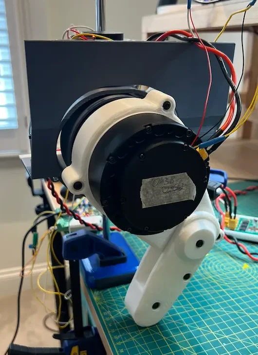
I recently assembled the full leg and hip assembly together.
The prototype was to trial the four motors, the assembly, and get an initial read of the software control.
The System
The mechanical system is made up of:
- Left hip lower assembly
- Left leg assembly
- Retort stand and mounting bracket
The electrical system is made up of:
- 2 x GIM8115-9
- Hip pitch/flexion
- Knee flexion
- 2 x 4310-36
- Hip roll/adduction
- Hip yaw/rotation
- CAN transceiver (TJA1050 based module)
- STM32F469NI Discovery Board
- Power distribution board (from earlier post)
- Quadcontroller (as from the Head prototype)
- CAN network and power wires
- Power supply
The leg assembly is the same as the previous prototypes. I’m currently working on updating the CAD to improve the design.
The retort stand provides a central support. Hopefully, it will allow me to test the robot moving itself vertically in future development. The mounting bracket just provides an interface between the vertical shaft and the hip assembly. The clamp is to hold it suspended while it can’t hold itself up.
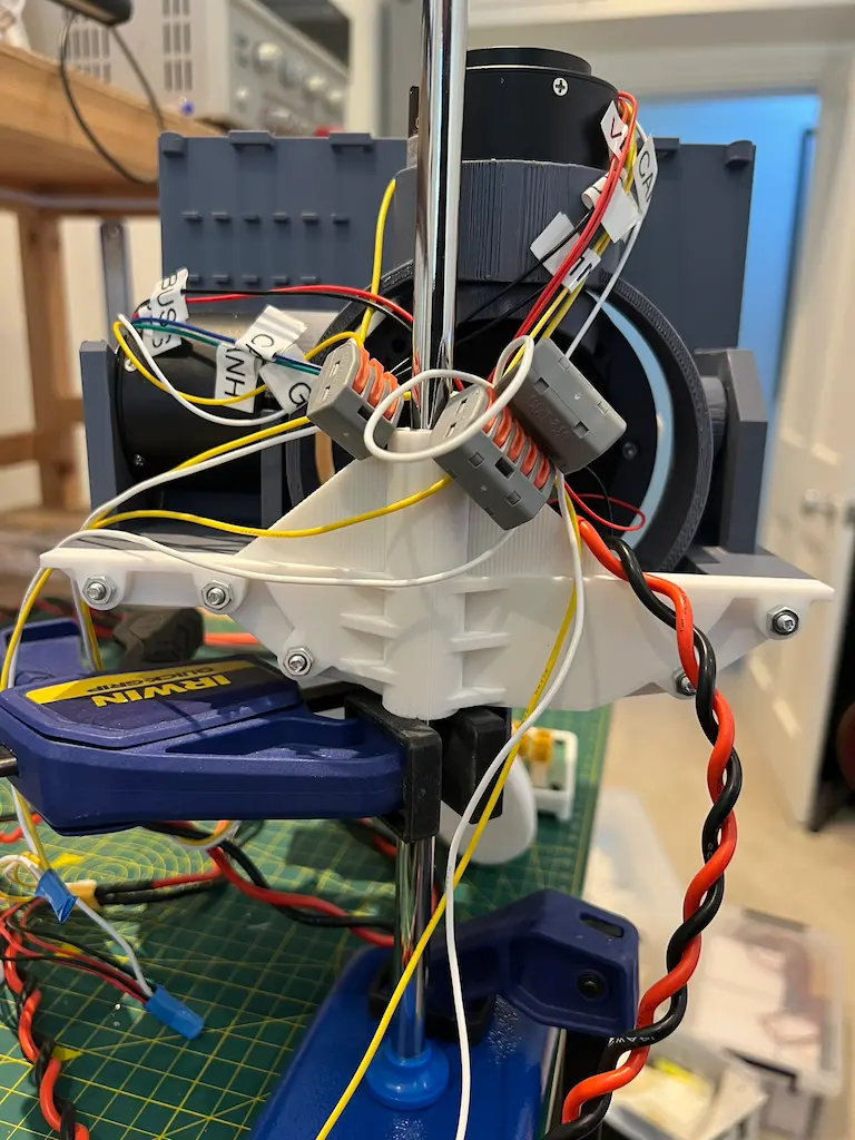
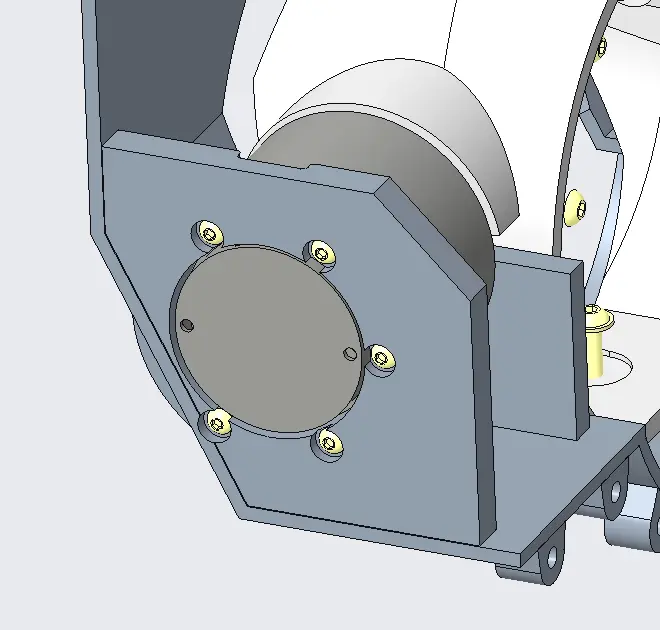
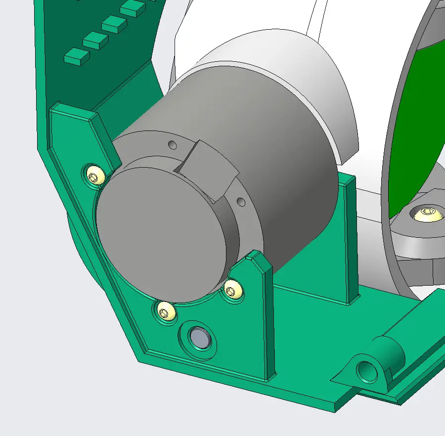
The hip lower assembly has had a few modifications since I received them, not all intentional.
The issues were insufficient spacing for the roll motor between its mounting brackets and being able to assemble it in place. I made some rough mods with side cutters to get it to fit. The CAD mods are looking a bit tidier.
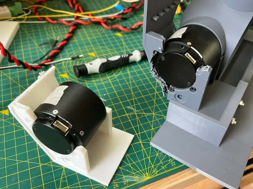
The other was from a roll motor moving a bit beyond what it should’ve. It expanded some of the mods I made earlier. It’s made it quite a bit more flexible so I currently don’t trust it to hold the weight of all the motors, and leg assembly.
The control gains set on the motor driver were all adjusted to be in line with each other. This seems to have helped with the oscillations seen in the earlier videos.
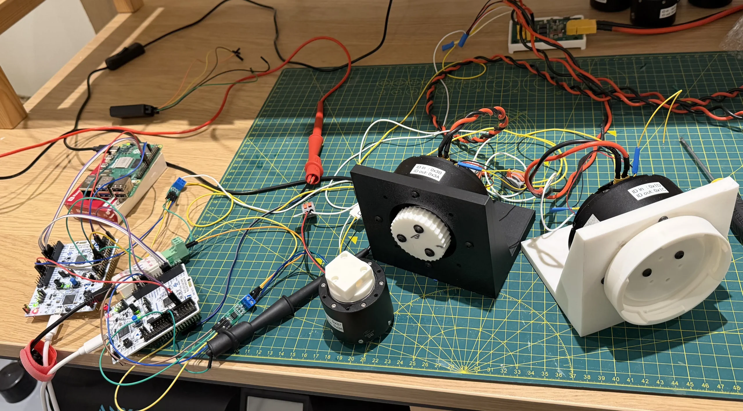
Electronics
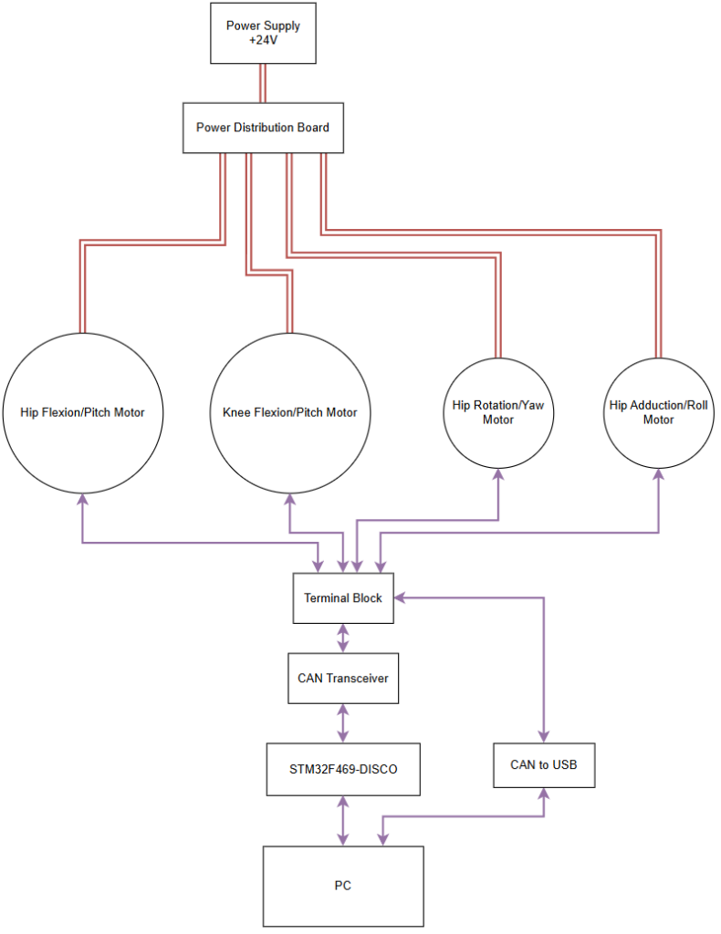
The electronics set up isn’t too complex.
With the various modules it was mostly setting up wires to connect between for CAN or power.
For Power
This was power coming from the distribution board for the 4 motors, with input power coming from one line of the power supply.
The 2 larger motors had their own harnesses, direct to the power distribution board.
The 2 smaller shared power through some terminal blocks.
For CAN
The motor wires were all connected through two more terminal blocks, with an additional set going to a ‘USB to CAN’ device for debugging and another to the TJA1050 module which interfaces with the STM32 discovery board.
The SteadyWin motors come with termination resistors pre-installed, I needed to remove two from off the motors to keep it to just two on the bus.
Running with 3 motors, each with termination resistors, worked inconsistently which lead me to look elsewhere for root causes for the issues I’d come across (having just two solved almost all the issues I’d encountered).
Software
The software was all running on the STM32 board. The STM32F469NI-Disco was chosen purely as I had one and it also had a CAN bus peripheral ready to use.
Set up as a state machine, after it’s done the initialisation it enters a calibration stage, which can then be toggled to a running state and vice versa.
The upper and lower limits for each joystick were measured separately outside of the program (with the same STM) and used as constants.
Calibration
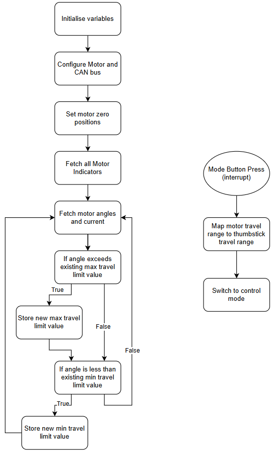
The calibration process runs in an endless loop until being switched to run.
Prior to the loop starting, during initialisation phase, one of the things the motors are queried for are their current positions which is then set as their zero-position. I don’t think it’s how I want to keep doing it, but it works for this prototype.
During the loop, the motors are queried for their positions repeatedly. Each motor’s position is then compared with a max and min travel limit recorded. This requires me to shift the joints through their allowed physical range of motion to get actual meaning into the max and min values.
With the next bigger prototype build I intend to set up a proper calibration process to set the limits then have them saved on the device.
Once the range of all joints has been swept through, a button can be pressed and the system shifts to the running state.
As it transitions, the motor and controller travel range are used to calculate a linear mapping from one to the other.
The calibration process leaves plenty of room for variation between trials. To minimise chasing ghosts later due to differences in calibration, I want to work through a better process for this (with some jigs) and more permanently store the calibration data. This would mean I can start up the robot each time knowing where it stands on calibration, until I change something.
Running
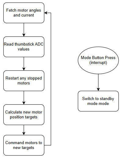
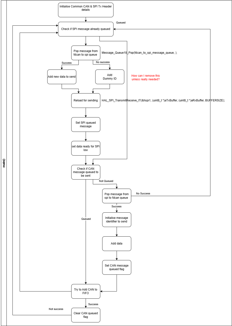
The running state has two main steps
- Read the thumbstick positions from the controller (second in the block diagram)
- Send the position command to the motors (bottom of the block diagram)
The thumb stick position is again done through the ADC, reading the voltage which gets passed into the mapping function.
The position command takes the calculated value and packs it into the standard message protocol.
One part of the position control command is the position value, the other is a duration, that is the time it should take in milliseconds to get to the position. This appears to have a minimum value of 1ms which will mean I need to set the position I want at least 1ms prior to needing to be there.
It may be that switching to velocity control and repeatedly checking position may provide the control I’m after. I expect this will need to be paired with a state estimator.
CAN Communication and the SteadyWin Protocol
For the python versions I had already written a format of a driver for the motors. I took this library, converting it to embedded C.
Having a CAN to USB device on the bus, with the occasional use of my oscilloscope, was crucial to debugging the system.
It gave a solid indicator on where issues were, i.e. motor, dev board etc..
Setting up the CAN bus was reasonably straightforward with various Youtube videos, the CubeMX code and documentation.
The filters and how the hardware manages inbound messages does have some lack of clarity in the docs and I’m still evaluating which type is the most effective for my application. For now, I’ve settled on specific must match filters for the chosen IDs the motors send out.
I will admit I did get tunnel vision on one area of data, the actual received message, and neglected/forgetting the receive header and the information it can provide.
One issue I am still challenged with is ensuring the information I need and/or want to be transferred is being done successfully within the needed or relevant time frame.
With a single motor this is less of an issue as long as the signals are clear and at a rate the bus can handle.
With multiple motors it becomes more of a problem with bus arbitration going to the lowest ID.
The motor driver software documentation doesn’t specify what the device’s approach is if it loses arbitration.
The prototype stripped back the information I was trying to send to and receive from the motor, as well as running it with a different rate as the main embedded loop and also sometimes off set from each other. Based on some recent reading of Josh Pieper’s mjbots blog, a deep dive might be necessary to set the CAN up in a robust way for when all 9 motors are connected and running.
Another issue that is not documented is if a start command is sent to a motor whilst already “started”, the response says it has failed.
This means the code needs to manage a “failure” result when the system is already in the target state.
The only method I’ve determined to check if the motor is running are a selection of indicators (all floats) become zero when “stopped” or non-zero when “started”.
Unfortunately, I’ve not been able to ensure that the value I’ve received for these indicators is up to date and reflects the actual state of the motors.
As I develop the control board, I want to further work through the CAN bus strategy, potentially splitting the motors across more than one MCU.