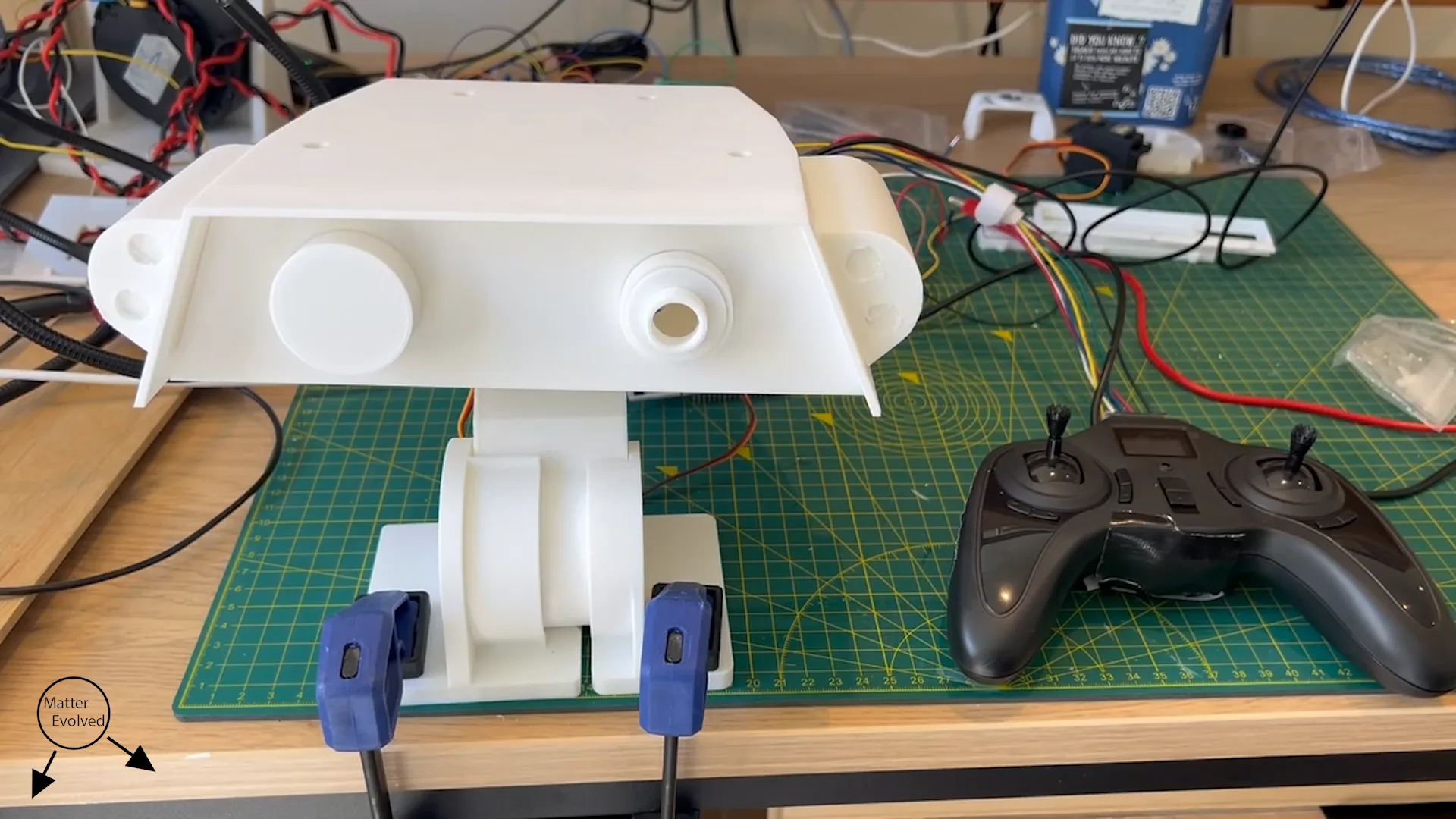
The head prototype was built to verify a few aspects:
- Check how the parts fit and moved together
- Confirm that the servo motors are powerful enough to move the head and with sufficient speed
- Have a software base to start growing from
The prototype encompassed almost all of the parts from the Head and Neck assembly.
Some parts had printed cosmetic replacements in lieu of the functioning parts:
- The camera lenses, printed as part of the face plate, with no modules
- Rear panel LED, mechanical sizing and estimate for electronic components
- Head torches, plastic shells with attachment intent
All the plastic parts were printed with PLA on my FDM printer.
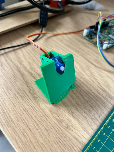
The servo drives were manually controlled through a hacked quad-copter controller and a Nucleo C031C6, both of which I had lying around.
Three of the thumb stick axes are directly mapped to the heads yaw pitch and roll.
The head range of movement was less than the roll and yaw targets of ±20°.
I wanted to keep some clearance with the rough control and the thumb sticks had some noticeable range between them.
I didn’t install the head yaw bracket in the prototype. This holds a bearing to help retain the yaw servo. This was due to me being lazy and the connection to attach it being too fiddly. There was no issue but I still want to include a version of it for structural piece of mind.
Initial Issues
The prototype had some issues show up that required some hand mods to allow full assembly.
The retention ribs for the face plate on the upper and lower head had a small interference.
The lower head clearance around the yaw carriage didn’t account for the neck above and below when rolling.
(Head clearance image)
I also measured the small antennae servos poorly when creating their CAD, this meant they didn’t fit in the pockets.
A second smaller prototype has shown I this now works.
Block diagram
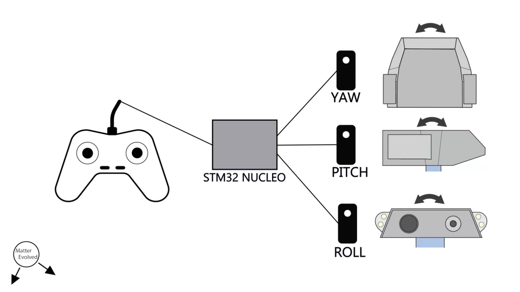
The system itself isn’t too complex.
It consists of several parts
- The controller, providing the head pitch, roll, and yaw target
- The STM32 Nucleo C031C6, reads the ADC values and sending the calculated pulses
- The servos, moving the head from the received pulses
- The power supply, not shown, which provides +5V to each of the servos
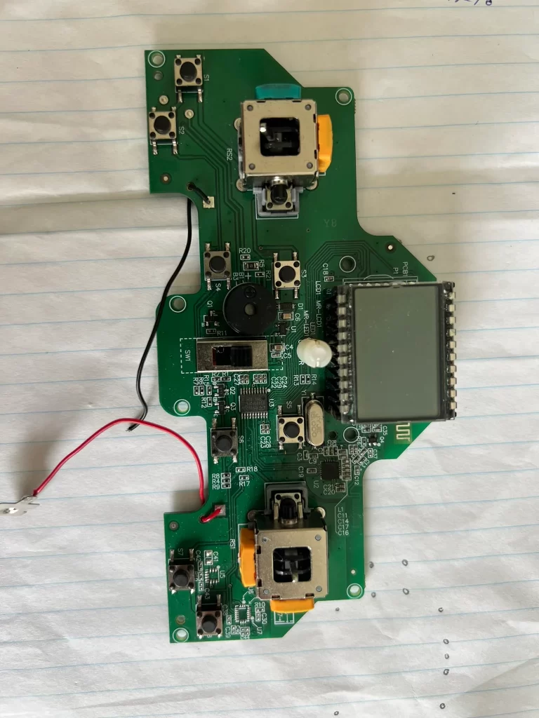
Controller
The controller came from a Hubsan X4 H107L RC Quadcopter with the quadcopter already having been torn apart.
The controller thumb sticks work by moving a rotary potentiometer per axis. Each was set up to have 3.3V at one end, and 0V at the other.
Each thumb stick then moves between these limits, with the voltage being read by the STM’s ADC.
Three of the axes were sprung to return to centre, the fourth not. For this prototype the non-spring wasn’t used.
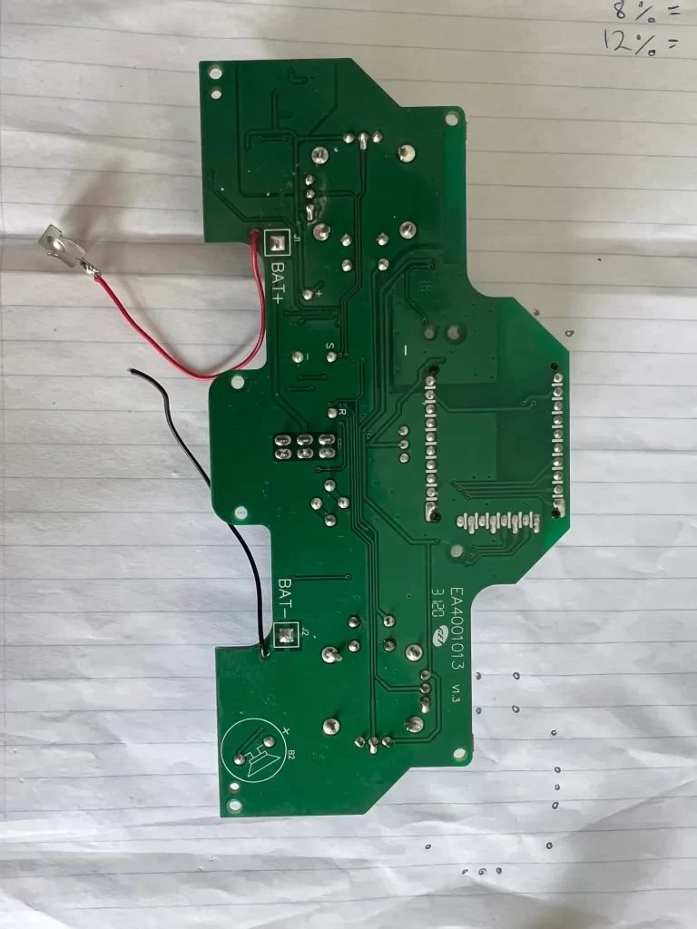
I determined which traces were connected to the potentiometers, cut the traces to disconnect these from the rest of the system, then soldered new wires to allow connection to the Nucleo.
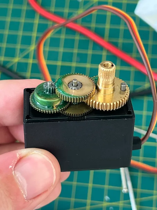
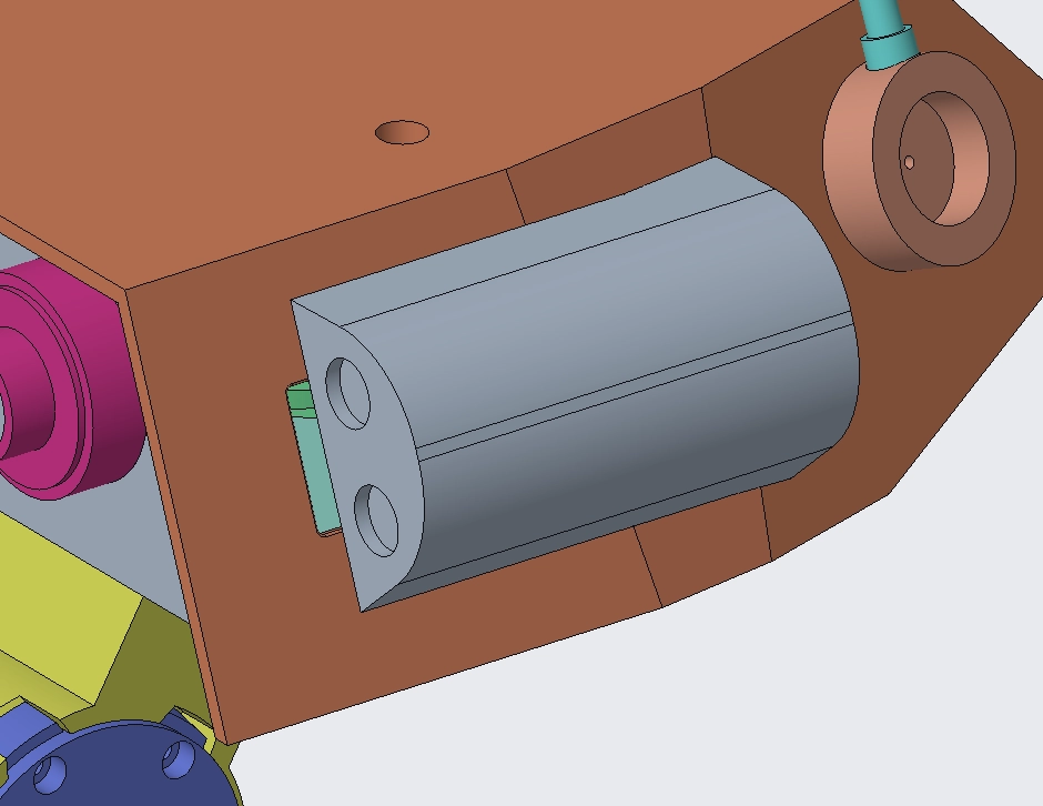
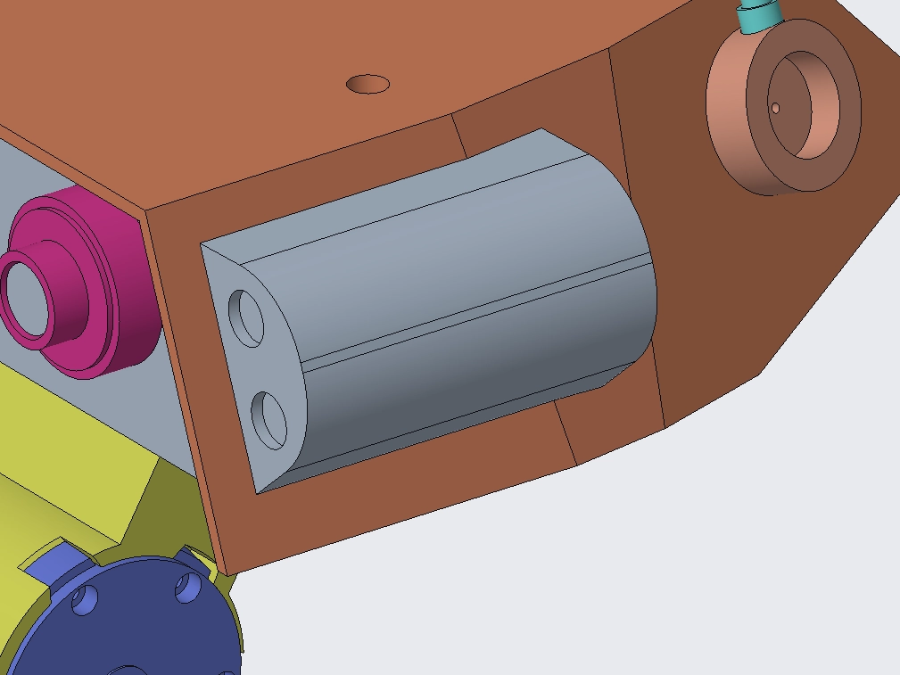
Servos
The servos used were Diymore MG996R which I’d purchased from Amazon some years ago.
They have a supposed stall torque of 13kgf.cm at 4.8V so hoped that these were going to be sufficient.
The output resolution isn’t as fine as I’d hoped. With the size of the head, the step increments are definitely noticeable.
The other issues I have had are with oscillations, it was quite common to move to a set point and the head oscillate back and forth.
There were also times where the servos would just drive to a random point, I’m not sure what caused this but definitely something I hope to root cause.
Interfacing to the robot parts is through a metal splined shaft with a press fit into the FDM parts.
The servos came with horns with matching splines, however, my FDM printer cannot replicate these.
Some of these connections loosened with use, the worst being the head pitch, so I may need to either integrate the servo horns or find a more reliable way to connect. Ideally it would be something removable and not akin to gluing in place.
[Servo image]
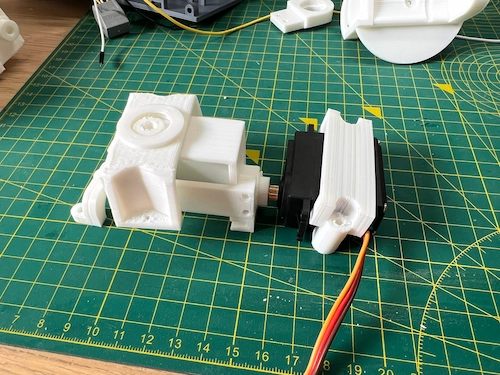
When installing in the prototype, I sent a PWM signal to set the servo near the middle of its travel range. Each servo was then installed close to its middle position. This allowed me to use the same PWM ranges for each and know there wasn’t going to be any drastic clashes, at least from this.
Nucleo Software
There was some variation in the end point and mid points between the thumbstick channels. As I wasn’t needing something super accurate I allowed for some tolerance in the conversion from position to voltage to control signal.
With multiple ADC signals the STM ADC was configured in a discontinuous scan mode.
The range of the thumbsticks were then scaled to approximately ± 18°.
CAD updates
Compared to the previous post, the head design size had to be reduced.
When it came to printing, the upper and lower head parts were bigger than the printer bed size so needed to shrink length and width.
I think I’ve maintained the same feel while being able to avoid printing it in more parts.
I’ve recently set up a new printer but will keep the head size unless I need additional space.
Beyond the overall volume, the changes to the CAD have been
- The rear LED panel
- The torch module attachment
- Fixes for clashes
- Antennae servo spacing
The rear LED panel
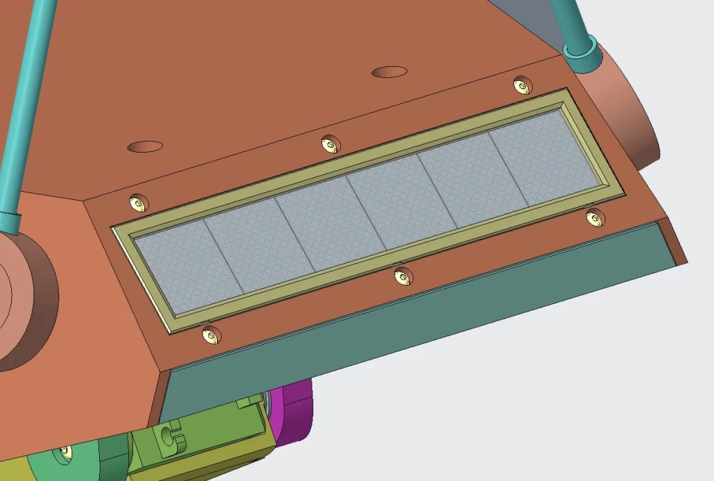
To refine the CAD in this area without an actual electronic design, I found some LED dot matrix modules and spaced them out with my design intent.
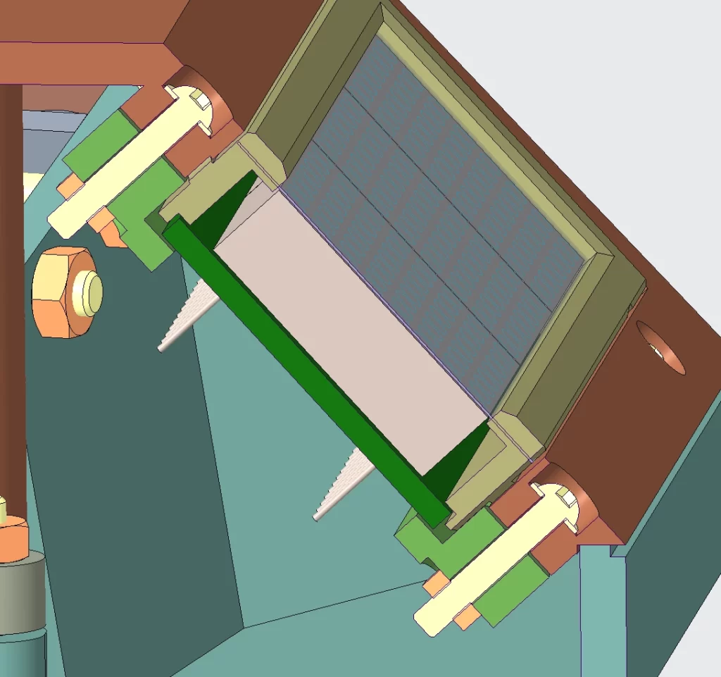
I want to include a thin layer of vinyl over these to help protect from anything being spilt on it.
To achieve this I need to clamp the vinyl over the PCBA.
With a final PCBA design, I’ll need to refine this area.
Torch attachment
The torch is installed with a sliding motion and secured in the position with a magnet on each of the head and torch.
It relies on two ribs and slots to help align the parts as it is slid forward.
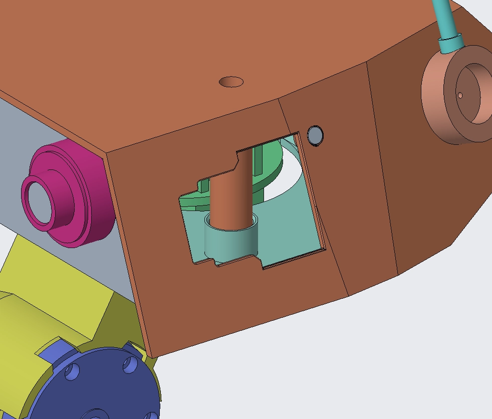
Clashes
The worst clash was between the head lower and neck when trying to roll.
The original circle around the yaw carriage in the head lower was expanded to more of a racetrack shape.
The actual size was determined through rotation of the neck in CAD.
It’s been kept symmetric but as I review and iterate the assembly between the upper and lower neck and overall use of screws this will also likely evolve.
Further improvements from prototype
Beyond those mentioned, in terms of further upgrades there are a mix of must-haves and nice-to-haves.
Must-haves:
- Wiring has been neglected but definitely needs to be incorporated as I refine the whole droid’s control and power architecture
- Review of assembly order, make sure that I can easily open and access the configurable and control system parts
Nice-to-haves:
- Most of the parts are held together with screws and nuts, I’m going to look at replacing the nuts with threaded inserts, and built in retention features to speed up assembly and disassembly.
I think I can cut down the number of screws which will hopefully lessen the assembly pain later. - The connection between the upper and lower neck is a bit clunky, I want to review if there’s a more elegant way.
- Lots of potential finger traps to try to remove
- Maybe some better servos to eliminate the jumpy motion and random movements.
Elsewhere in the project
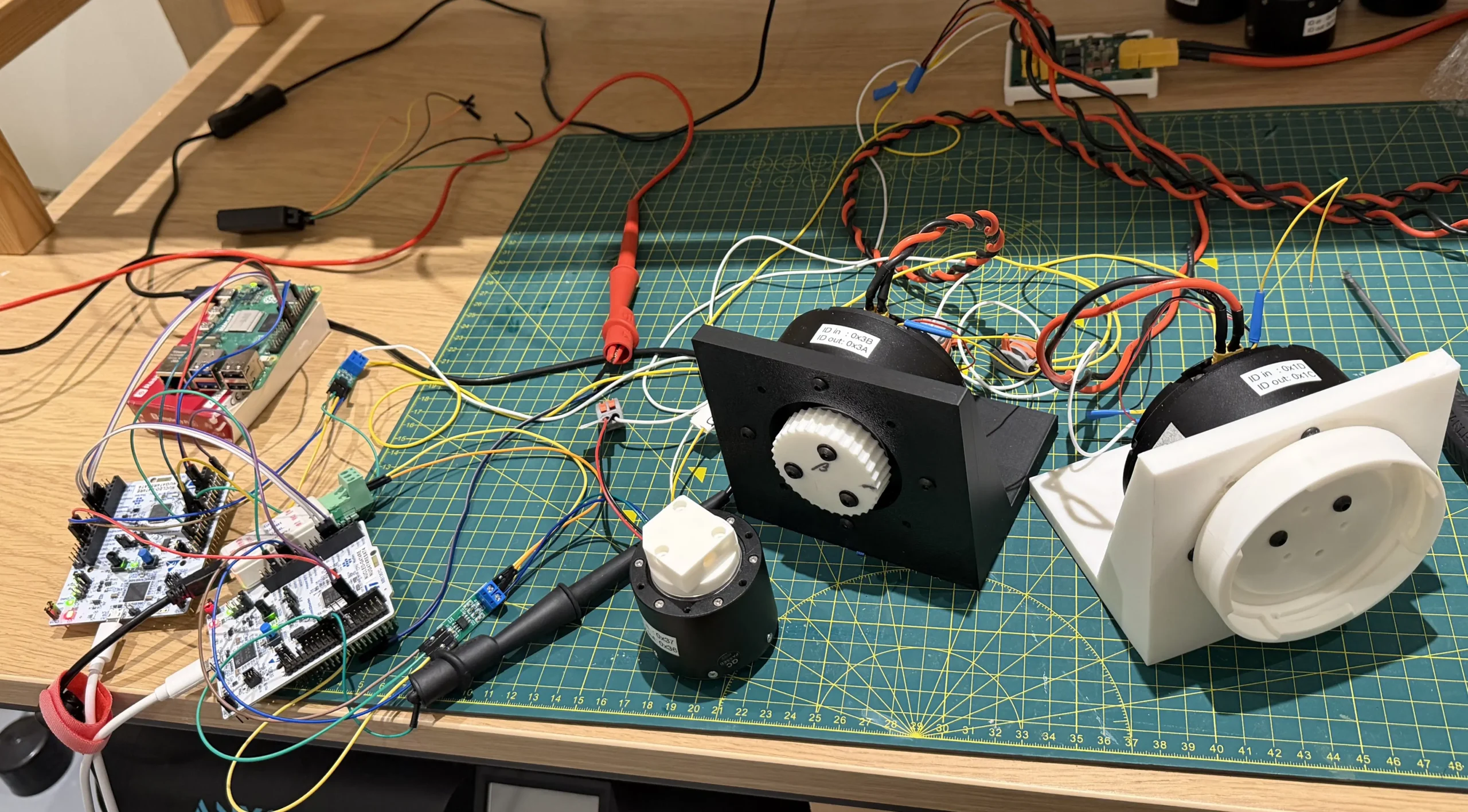
I’ve recently got 3 of the leg and hip servo motors working together.
A simple prototype with some basic calibration, simple back and forth movement, and data relaying is working. This is all being used through the power distribution board.
The next version is to have reuse the same quad copter controller to make set points and move the joints to for hip pitch, yaw and roll, and the knee joint.