Goal
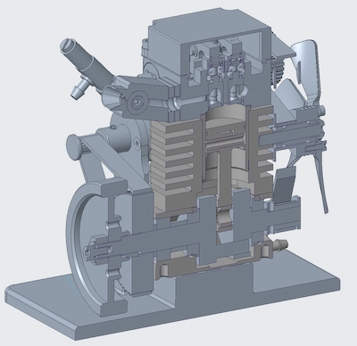
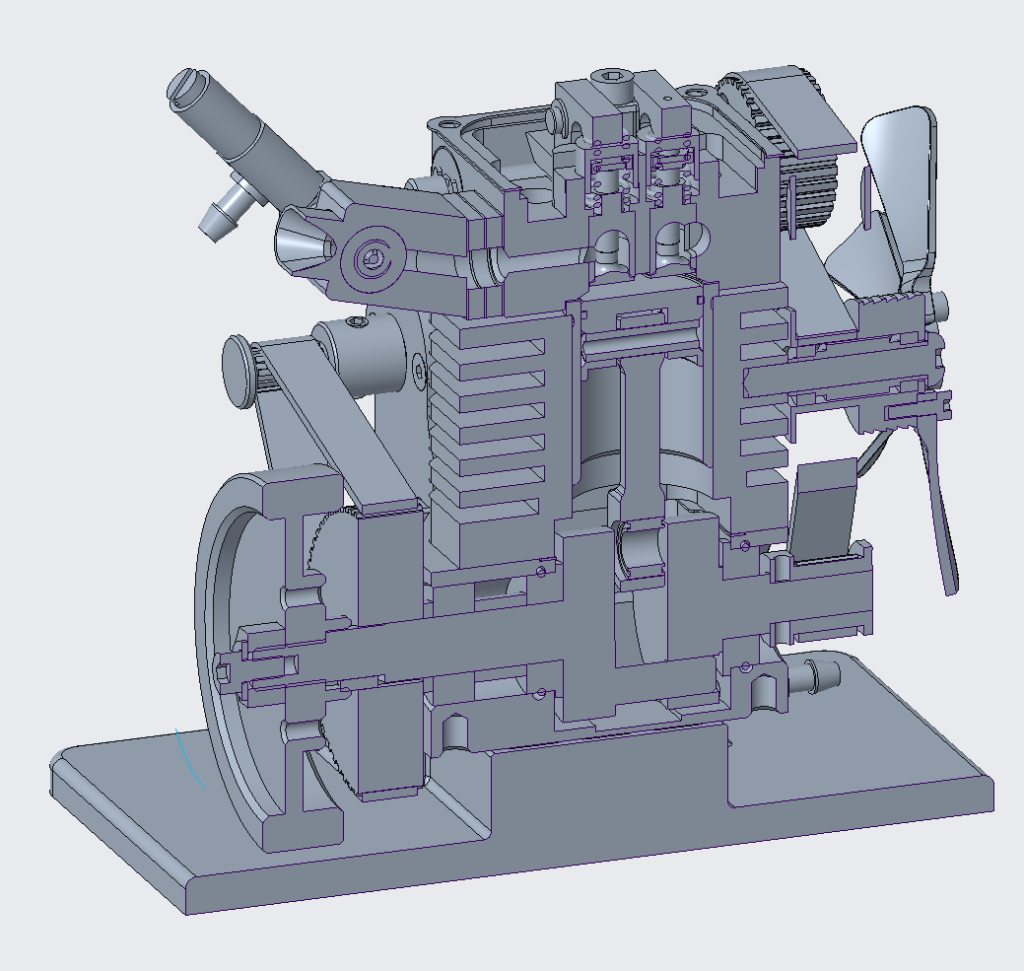
CAD the mini engine to create static and mechanism models.
Learn a bit more about ICEs.
Create a basis to dive into analysis of the engine.
This post will run through the engine and model at a high level.
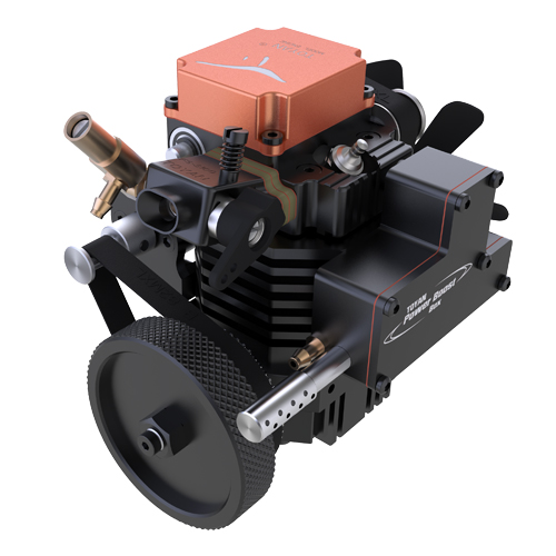
What is the engine?
Toyan FS-S100A Single Cylinder Four Stroke Methanol Model Engine.
Designed for 1:10->1:14 RC Vehicles
Cost $257.13 USD in 2022 (purchased from Amazon.com)
System Specs
Displacement: 3.5cc
Bore: 16.60mm
Stroke: 17.0mm
Practical RPM: 2200-10,500/2500-13,500rpm
Output: 0.5ps @ 9600 rpm
Weight: 382g
Size: 100.5 x 85.4 x 86.5mm
Spark Plug: 1/4-32 threaded ME8 type
Approach
Initially, I started building the CAD based on an assembly guide I found online, and a YouTube assembly video here.
This got me a big chunk of the way but lacked some of the finer details, especially in areas like the cylinder head.
Eventually, I bought the kit (which surprisingly came fully assembled), and started to measure and create the parts in CAD.
This certainly had some frustrations with the slightly bent vernier callipers and the large quantity of holes.
Engine Structure
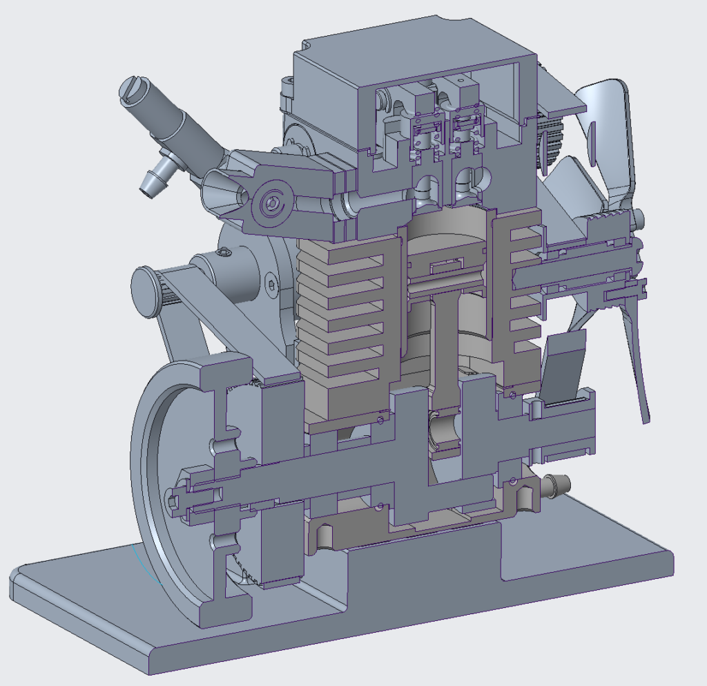
I structured the CAD into 7 sub assemblies based on structure and function
- Engine Body
- Muffler
- Carburettor
- Starter Motor
- Cooling Fan
- Cylinder Head
- Crankshaft
Engine Body
The physical centre piece of the whole engine.
A solid block with a couple of functions
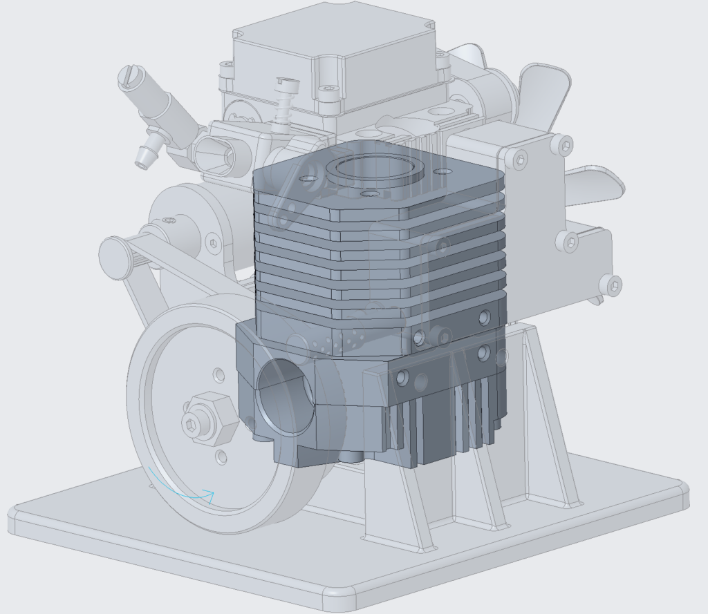
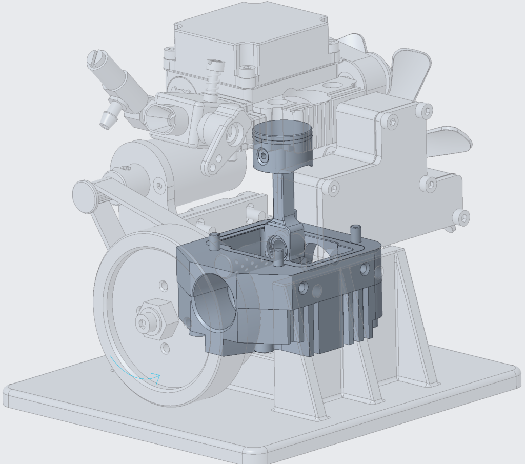
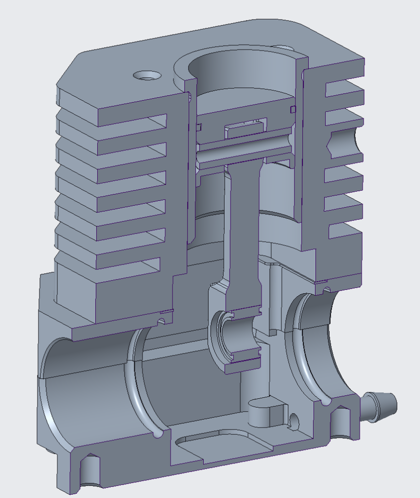
Everything is mounted onto this and/or interacts with it, either structurally or functionally.
Consists of:
- The piston
- Mounting holes and structure for the other sub assemblies and general mounting
- Combustion chamber
- Finned section for heat dissipation
Exhaust
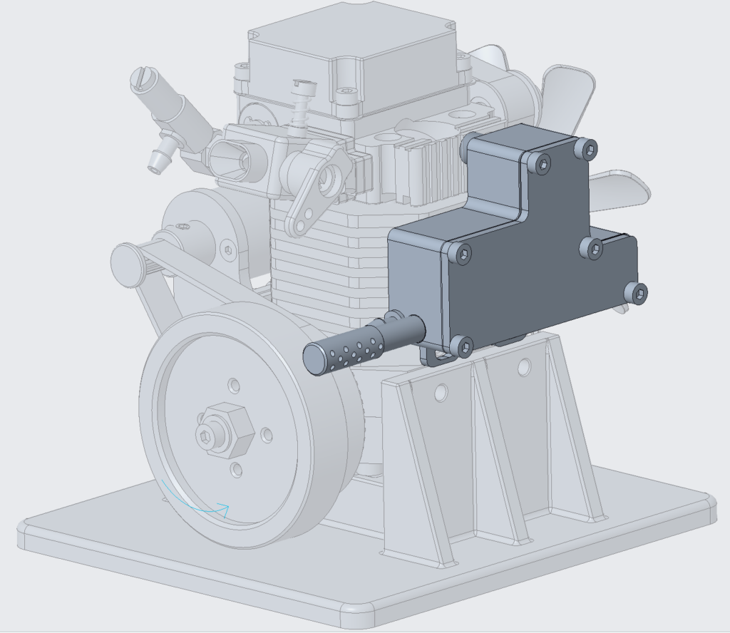
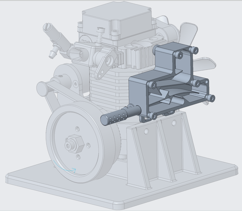
Two main aspects
- Convoluted air path, I assume it’s multi purpose to:
- Exhaust outlet
The convoluted air path seems to perform a few functions:
- Allow some time for the exhaust gases to drop in temperature and velocity
- Muffle the noise from the engine
- Collect by-products from the combustion or elsewhere as they fall out of the flow
Carburettor
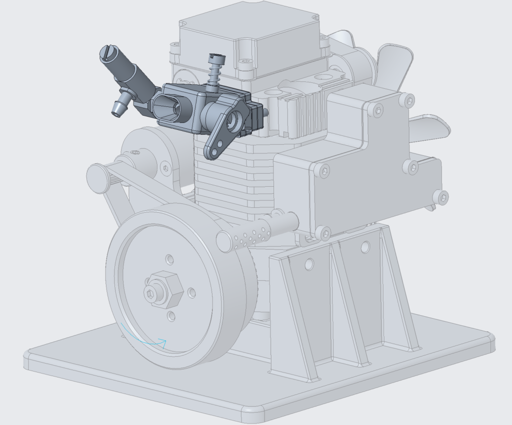
Lots of different pieces
- Inlets
- Fuel
- Air
- Throttles and other adjustment valves
- Dampening
Opportunities to adjust and control how the engine runs.
From allowing/limiting more fuel to allowing/limiting more air to be used in the combustion.
Some involve finer tuning with threaded interfaces to the throttle which can have a large play.
Starter Motor
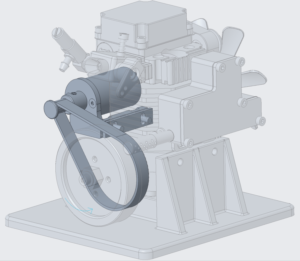
Basic electric motor with a timing belt connection to the crankshaft.
The pulley on the crankshaft is clever, it only engages in one direction.
When the engine is not spinning, or spinning slow vs. the electric motor, the electric motor is able to drive the crankshaft.
However, when the engine has accelerated enough, the pulley spins allowing no back driving through the timing belt to the electric motor.
During startup, once the engine takes over driving of crankshaft the pulley will be slipping and the electric motor can be unpowered.
Fan Assembly

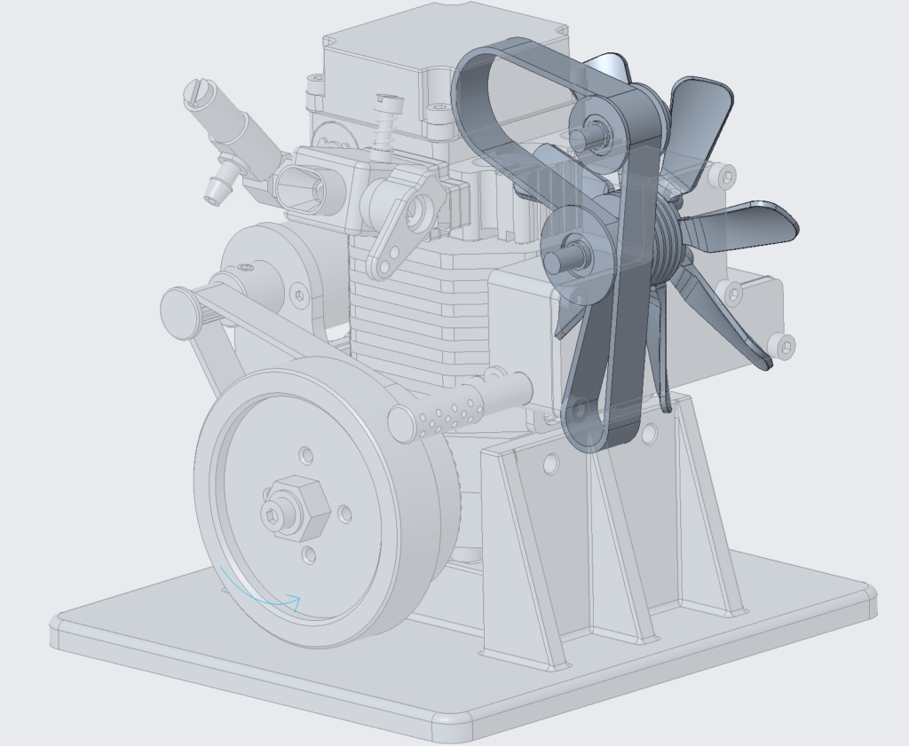
The fan assembly interfaces with the crankshaft and cylinder head assemblies through the camshaft with a timing belt.
To synchronise the timing between the piston and valves, the camshaft and crankshaft pulleys are aligned with pips on each pointing downward, the timing belt is then assembled maintaining these orientations.
As the timing belt is driven by the crankshaft, the fan is spun blowing air over the engine body.
Cylinder Head
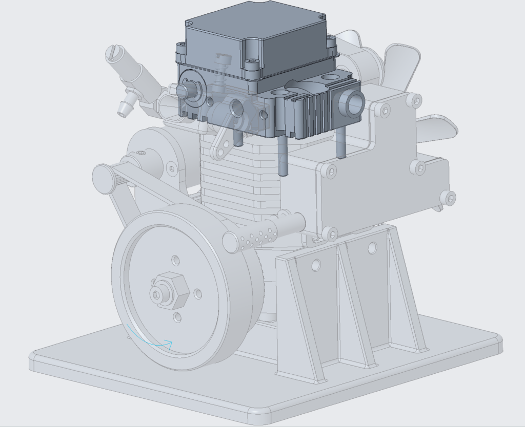
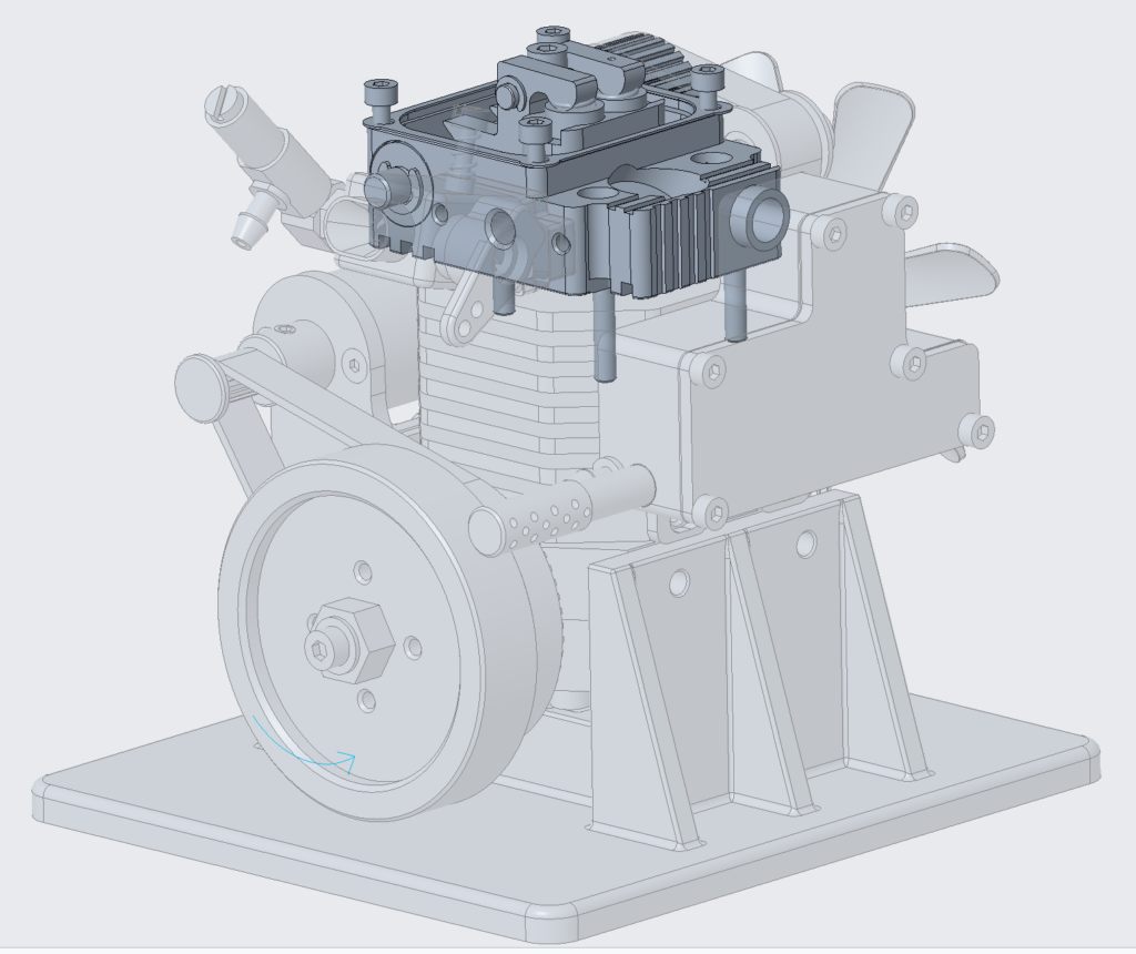
The most fiddly assembly to take apart, measure, and reassemble. Especially the inlet and exhaust valves.
The cylinder head has several sections
- The camshaft
- The valves
- Inlet, exhaust and upper combustion chamber
- The glow plug mount
The Camshaft

The camshaft is driven by the timing belt.
As the camshaft rotates, two cam surfaces actuate two rocker arms that are responsible for opening and closing the inlet and exhaust valves.
The camshaft surfaces are at 90degrees out of phase with each other, with the exhaust valve opening 90degrees before the inlet valve.
The Valves
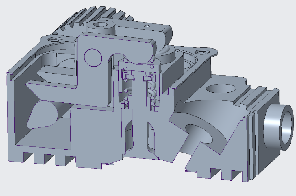
The rocker arms drive the valves by pushing down on the valve covers which in turn pushes the valve down and compresses the valve spring thus opening the valve.
This spring ensures the valve closes as the cam rotates away.
Inlet, exhaust and upper combustion chamber
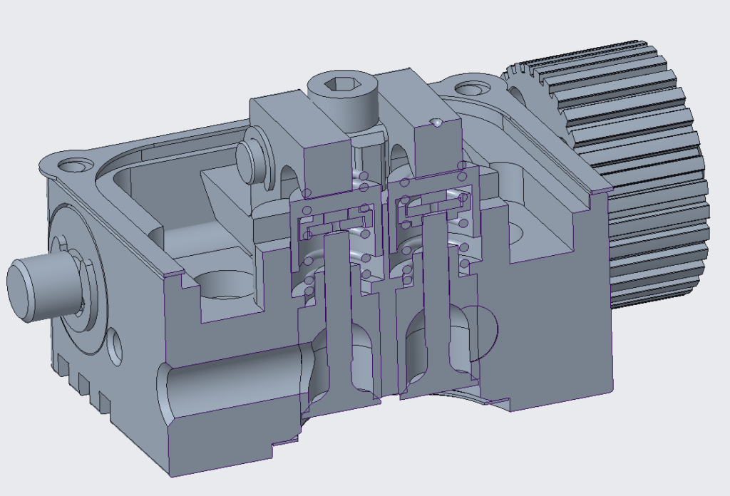
The inlet and exhaust channels are cut perpendicular to the valves, leading direct from the carburettor or to the exhaust system.
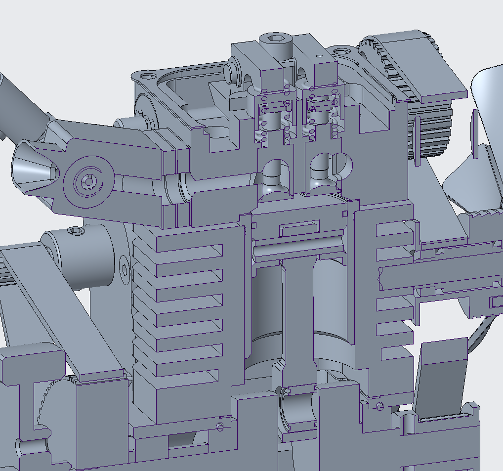
The upper combustion chamber is a small section of a sphere allowing space of the two valves and glow plug to sit above the piston.
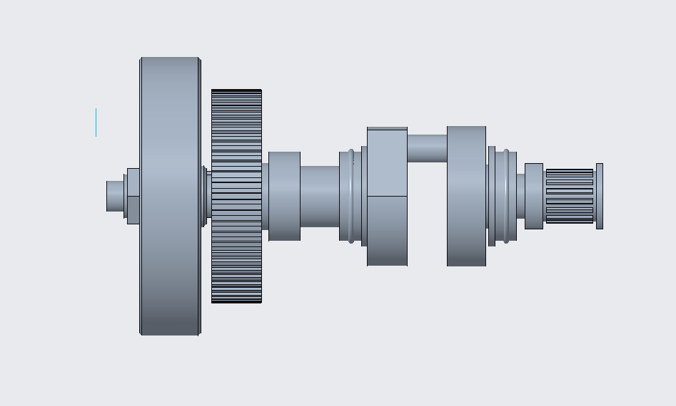
Crankshaft
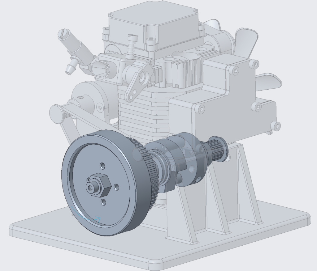
The crankshaft has a few key functions:
- Actuate with the piston, either pushing it up or transferring the energy from the combustion power stroke
- Transfer the starter motor input energy
- Output rotation to the fan and cam shaft assemblies
- The flywheel maintaining rotation with minimal angular velocity variations
The crankshaft is made up of two “halves” with two pulleys, a flywheel, bearings for mounting, and an eccentric shaft for attaching the piston.
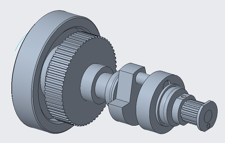
Running
The video where I discovered this engine:
DIY Garage – 4-Stroke Mini Engine Build & Start Up
Jump to 10:28 to see it running.
Future Plans
From here, I want to use this as a foundation to run some CAD analysis.
I would like to do this with Creo Mechanisms and also with more advanced software, such as Ansys.
For now, with other projects, I don’t expect to get to this anytime soon.
Until next time.

