Goal
- To learn more how engine/motor performance is measured
- Create a basic cheap dynamometer for home project use
Current Design
Components/Sub Assemblies
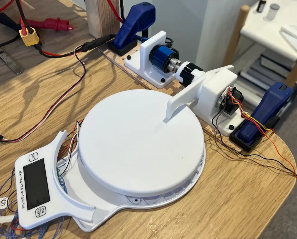
The dynamometer is currently made up of the following:
- A Feather 32u4 uSD Adalogger with 128×32 OLED Featherwing Display Module – Allows for a quick and simple interface and control of the ESC
- Electronic Speed Controller (ESC) – This is specifically for the BLDC motor under test, and will need to change dependent on the motor’s needs.
- Housings
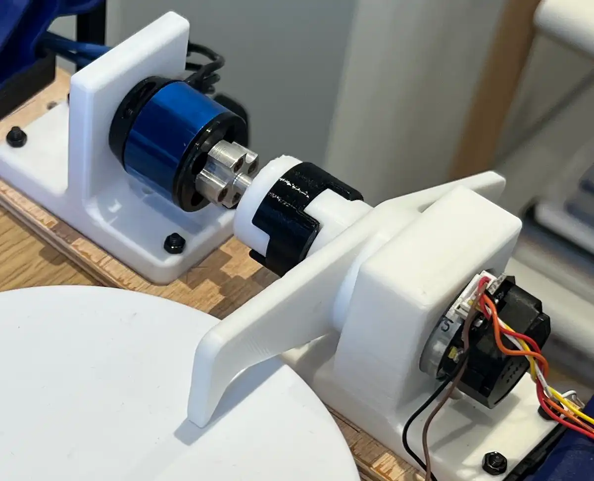
- Coupling – A TPU connection between the test and brake motors
- A Brake Motor – Provides a variable load and an arm to engage the load cell
- External Power Supplies – For the Feather board and motors.
What Performance It Measures
A motor has several different parameters that define it’s operating point and performance.
The common items provided, for a set voltage, by manufacturers include:
- Current, I (A)
- Output Power, P (W)
- Torque, T (Nm)
- Efficiency, n (%)
- Speed, (rpm)
Typically this is represented on a graph with Torque on the x-axis and everything else on the y-axis.
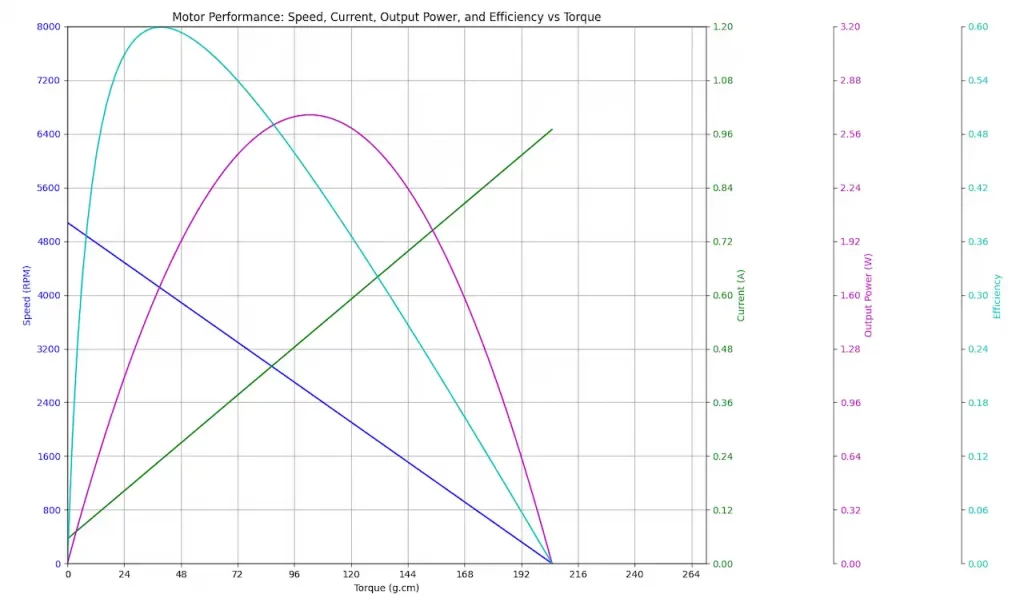
An example of a motor’s performance curves.
How it Measures
The principle of operation is as follows:
- An operation voltage is chosen (and ESC speed if applicable)
- The equipment is set up as in the picture below, including the motor to test.

- The brake motor provides a variable load for the motor under test
- With the test motor running the load applied by the brake motor is increased
- At various points recordings of measurements are noted for:
- Current
- Force on the load cell
- Speed
- Once you’ve swept the brake motor from no load on the test motor to zero rotations (ideally) the test can be stopped.
- The force on the load cell needs converting to Torque, with Output Power and Efficiency calculated from the measured values.
Video of the system running.
Future iteration ideas/intent
The current setup needs more to become a “usable tool” in my workshop.
Some of the current ideas and thinking I have for upgrades are:
- Integration with power supply
- Connect to my RS Pro power supply and automatically log the voltage and current linking with the other readings.
- To integrate this I need to understand what the ports and protocols are capable of communicating and designing how hardware and firmware can be added to incorporate this.
- Integration with the load cell
- Eliminate user steps and auto read the values for logging.
- An approach to coordinate with the displays clocked signals needs to be figured out.
Possibly using the displays row signals to drive interrupts (see the post for more info).
- Integration with speed sensor from the brake motor
- The brake motor includes a PCBA that is able to measure rotational speed.
Leveraging this directly would simplify work needed to get these values, or be used as a leaping point for my own design.
- The brake motor includes a PCBA that is able to measure rotational speed.
- A computer interface
- Being able to plug into the dynamometer with USB
- A simple GUI that can be used to
- start/stop logging
- drive the ESC
- drive the brake
- generate plots and tables of results
Reaching The Current Design
Initial design inspiration came from Jeremy Fielding‘s video of his dynamometer setup: How to Measure Horse Power for Any Electric Motor
Some Versions Made
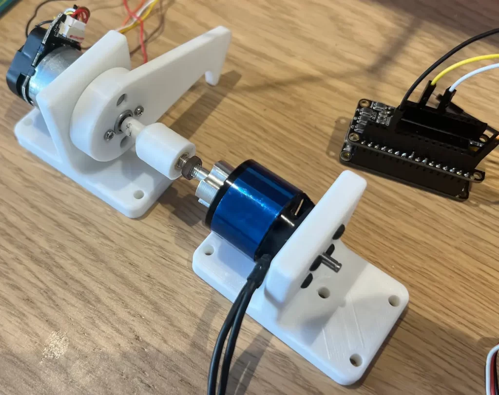
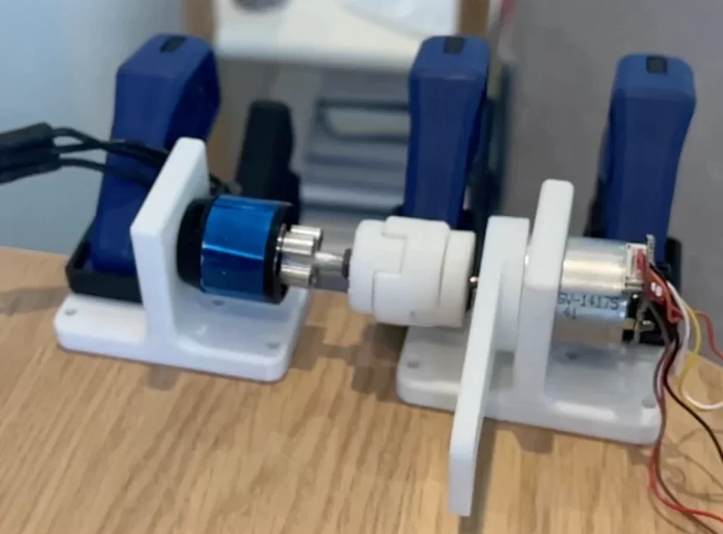
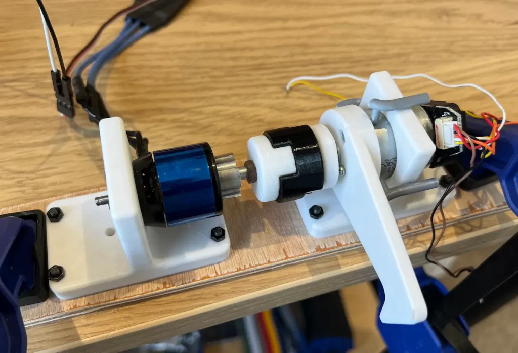
Housings
- Initial support for the brake motor was too thin.
It allowed lots of movement and vibrations as the motor could effectively pivot on the walls of the supports.- I glued on some plastic sprue I had, this helped a little but not enough
- The main improvement was thickening up the wall so the motor was more limited to:
- Roll around the axis
- Lateral movement along the axis
Coupling
- Initial designs and assembly approach were poor
- The couplings were very rigid which which contributed to lots of vibrations
- Assembly was hard to get good mounting and alignment
- Threaded inserts became offset to the axis
- Press fits became angled to the axis
- Changes made
- The coupling between the test and brake motors material was changed to TPU. This was the main reduction in noise and vibration
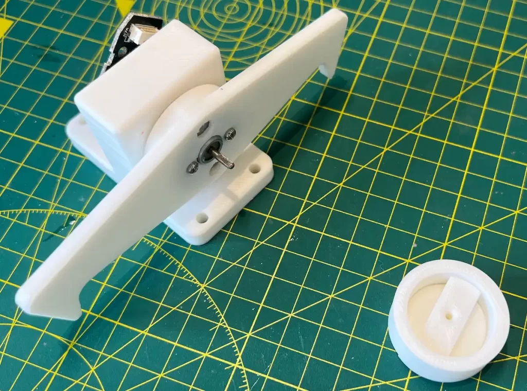
- An alignment jig was made for assembly, simple but super effective,
Was just a printed tube that restricted the angle the coupling could be when pressed onto the shaft.
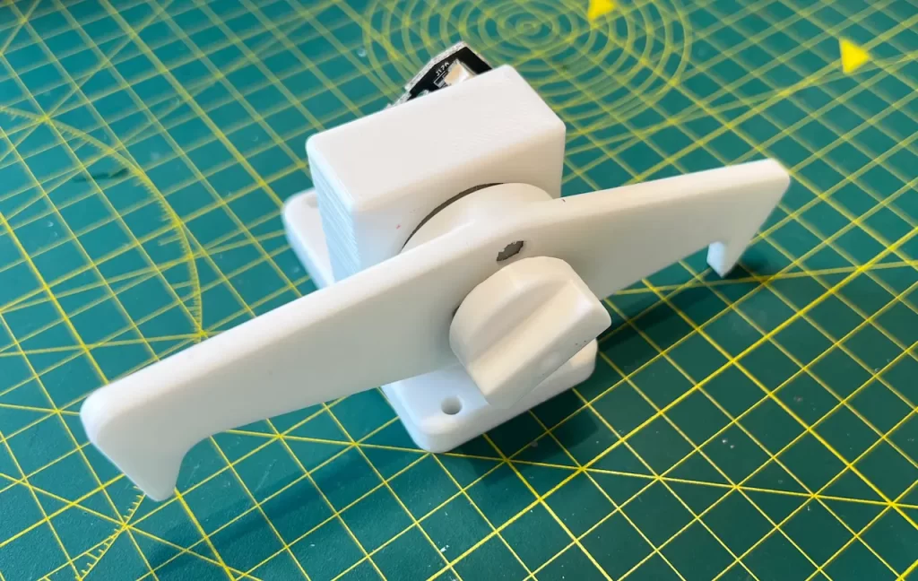
Lever arm
- Single side to dual side
- Simple change, was already printing other parts so why not
- Allowed more flexibility on load cell placement
Load cell
Intent was to use a cheap set of hacked kitchen scales to provide the required force measurements.
This development is captured in a separate post here.
Until next time.

