YouTube Video
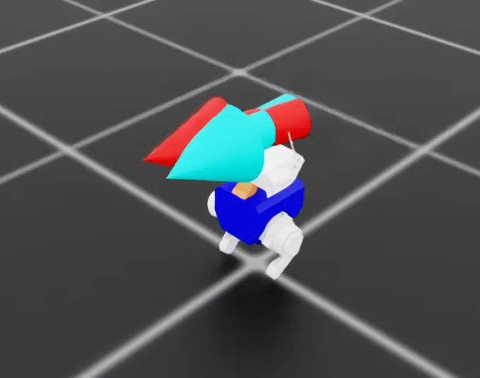
The Assembly
Primary goals of the sub assembly:
- Provide a mounting point for attaching the legs
- Provide two additional axes of hip motion per leg
- adduction/abduction (rotate leg inwards and outwards)
- medial/lateral rotation (rotate knee inwards and outwards)
- Form part of the left torso structure
Structure and Desired Performance
Leg attachment
Achieved through housing the hip pitch motor (previously shown as part of the leg assembly).
Assembly process of attaching the leg depends on partial disassembly of the femur (splitting the inner and outer femur parts), which I expect to be annoying when it comes to testing and adjustments of prototype parts.
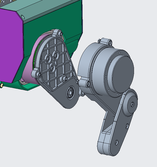
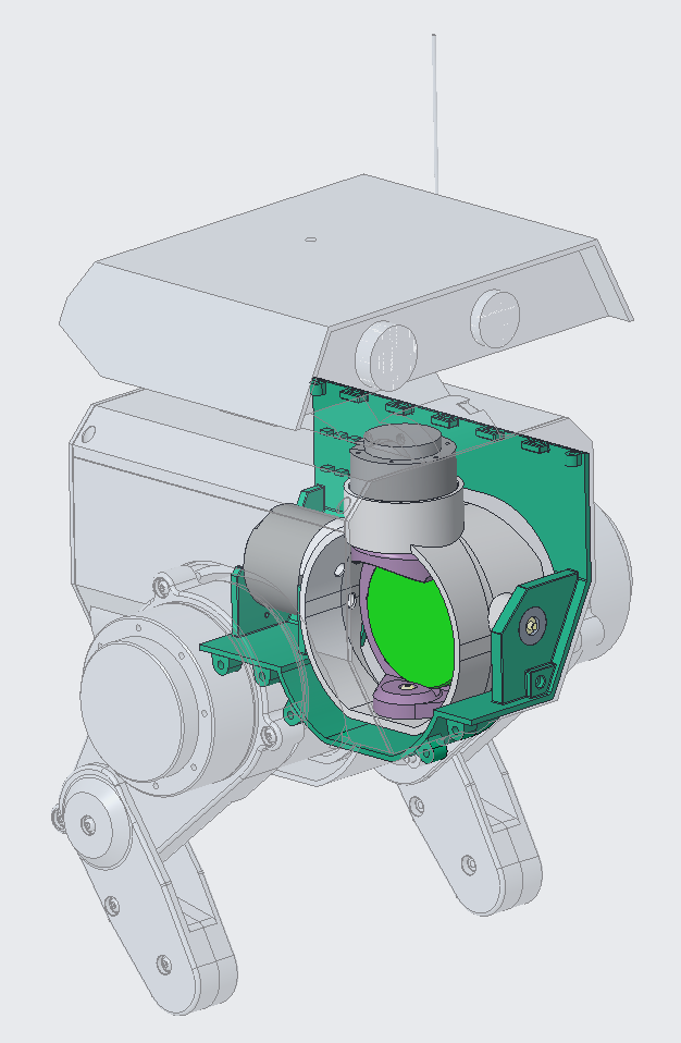
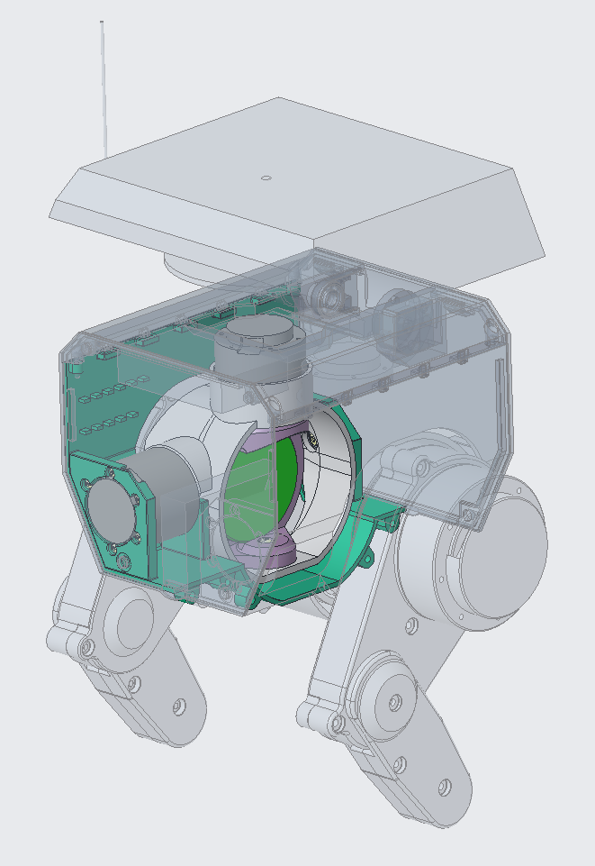
Hip Motion
Initial concepts were developed around the use of a linear actuator to provide adduction and abduction motion. The intent being to minimise size and cost of what was needed (also already having two on hand). Further working through the dynamics, the forces provided by linear actuators were falling short of what were needed.
Pivoting to using two motors, I had to identify smaller options than what were used on the legs to avoid a significant torso width increase. Dynamic models and movement ranges of +/- 5 degrees were used to determine torques and powers.
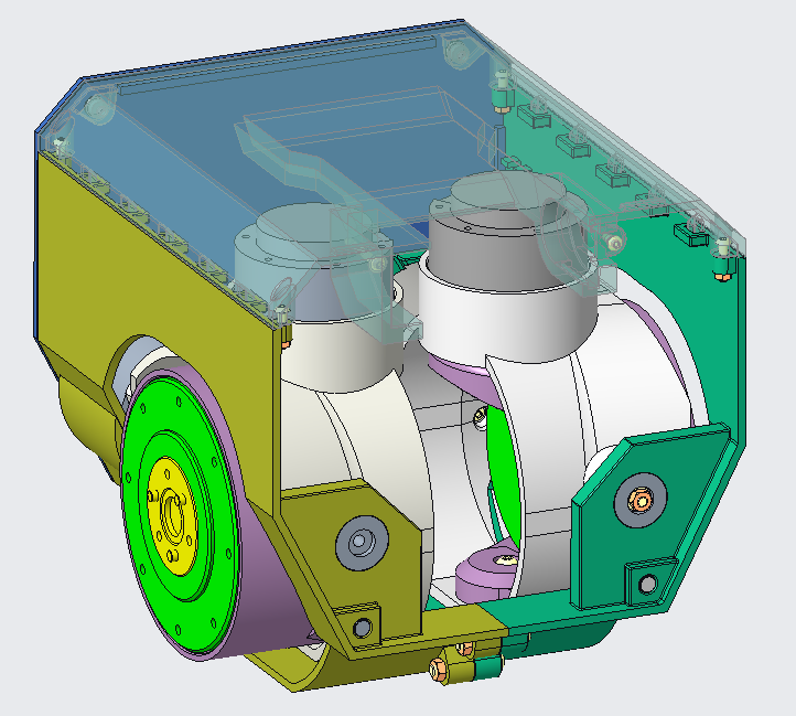
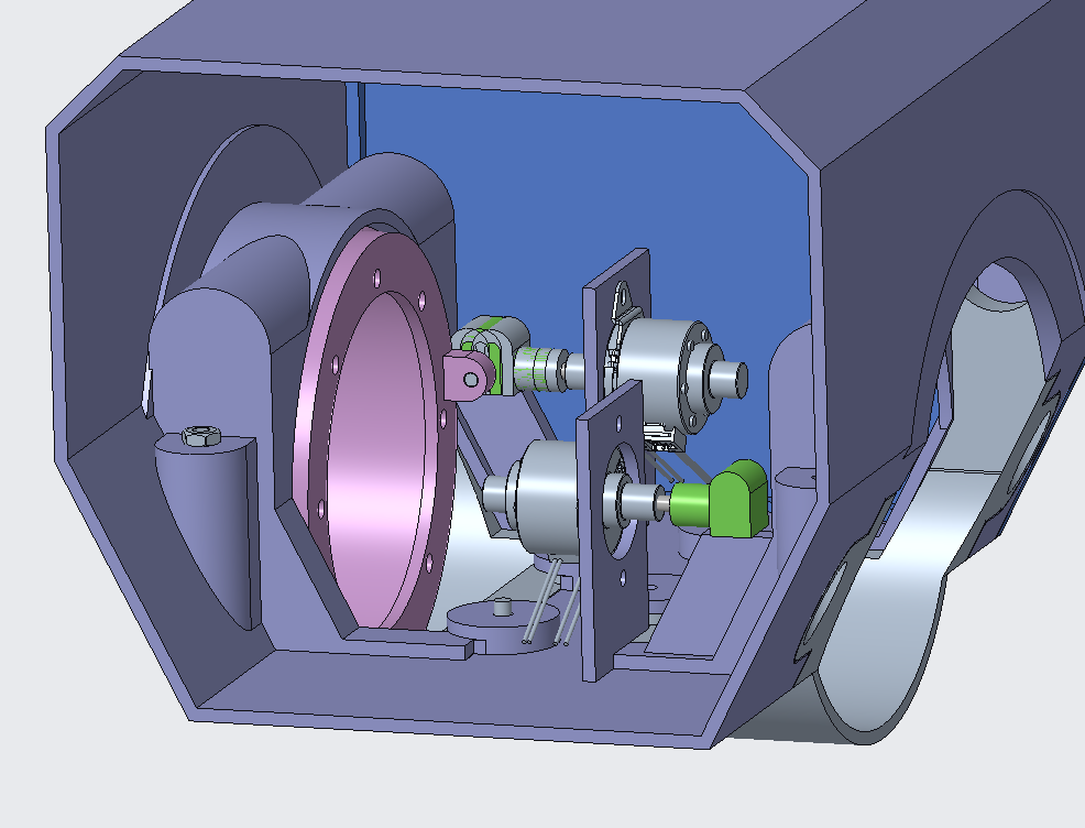
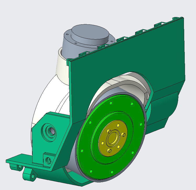
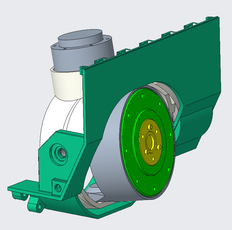
The architecture has motor order of roll motor (adduction/abduction), yaw (medial/lateral), then pitch (forwards/backwards). Pitch was bounded by the leg design, the order of roll and yaw were chosen to minimise the disruption/volume need within the torso for the motor movements. The position of the yaw motor and it’s corresponding roll motion envelope uses less valuable space than for the alternate setup.

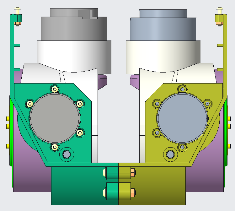
With the order set the housings and pivots were worked backwards to ensure sufficient clearances were given for the desired range of motion. The goal initially was ±5 degrees, for the design I pushed this to ±10 degrees. The limit to this is when both yaw motors have been rotated inwards (legs have been abducted outwards), as they cross the torso centre line they’ll collide. I don’t want to physically limit this for now unless this can’t be managed in software to maximise leg usability.
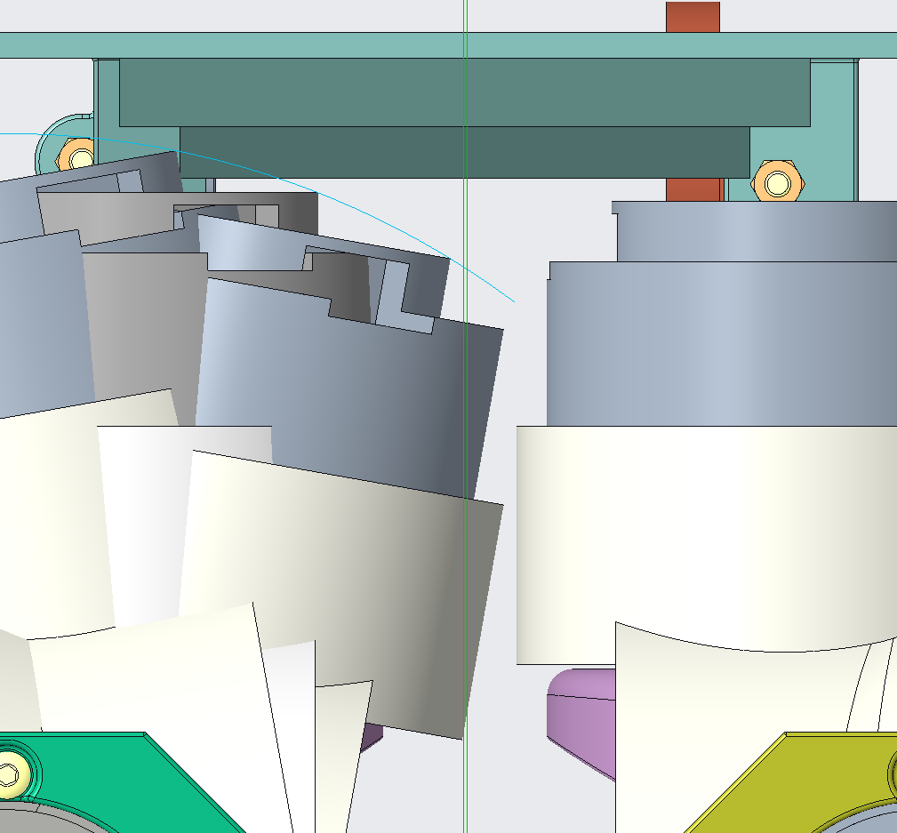
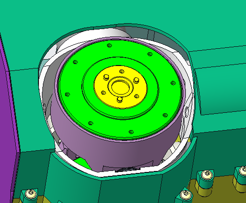
Images of motors and ends of travel.
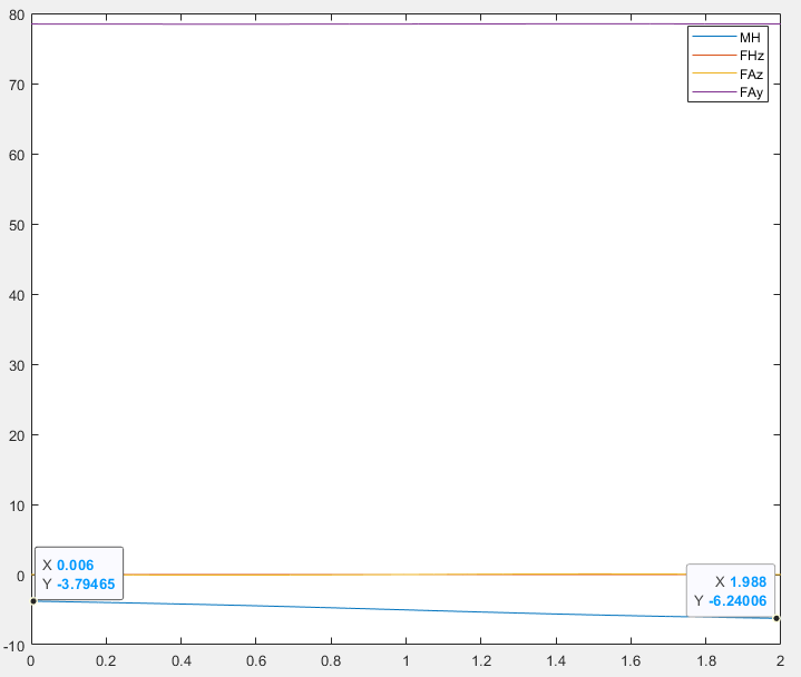
Sizing of motors
The dynamic model was based on the foundations from the leg dynamic model.
Values and setups were modified to reflect the different geometry.
I again relied on SteadyWin’s range of motors to identify one that was suitable with a package that isn’t too large.
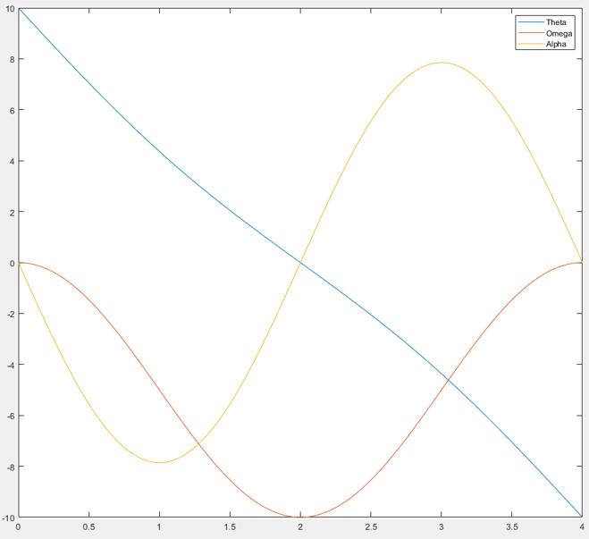
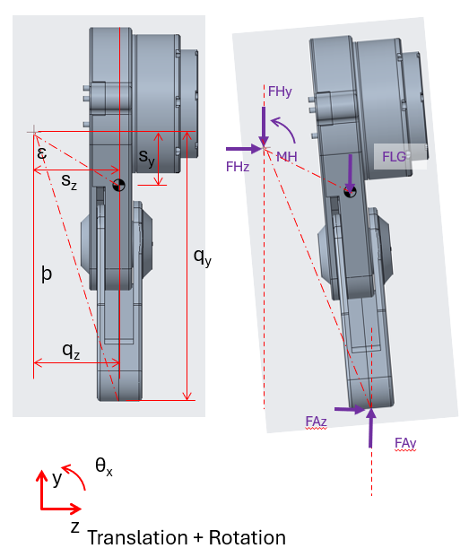
Angular displacement, Theta, is in degrees. Angular velocity, Omega, in degrees/second. Angular acceleration, Alpha, degrees/second/second.
Forces are in Newtons, and Torque in Newton Metres.
Torso structure
With the pieces needed to retain the pivot it naturally fell that the main body followed the cosmetics, being both outer body and structure.
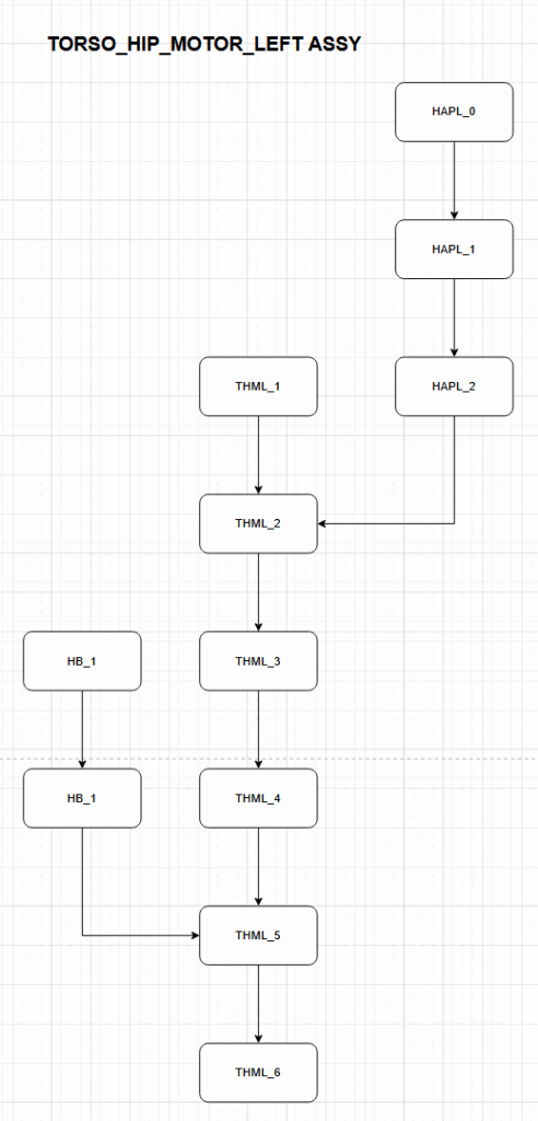
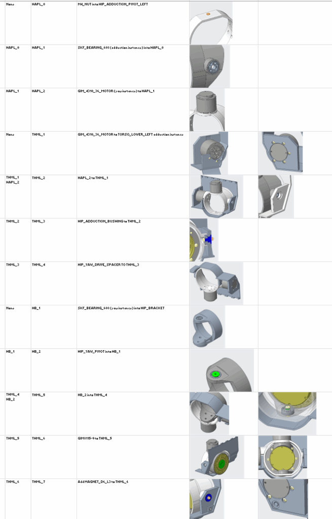
Assembly
With the various motors and their mounting points for the rotor and stator meant assembly was important to avoid producing prototype parts that could not be assembled or disassembled without cutting or gluing. An assembly order was worked through with modifications and adjustments made to achieve a (hopefully) working assembly process.
Future Plans
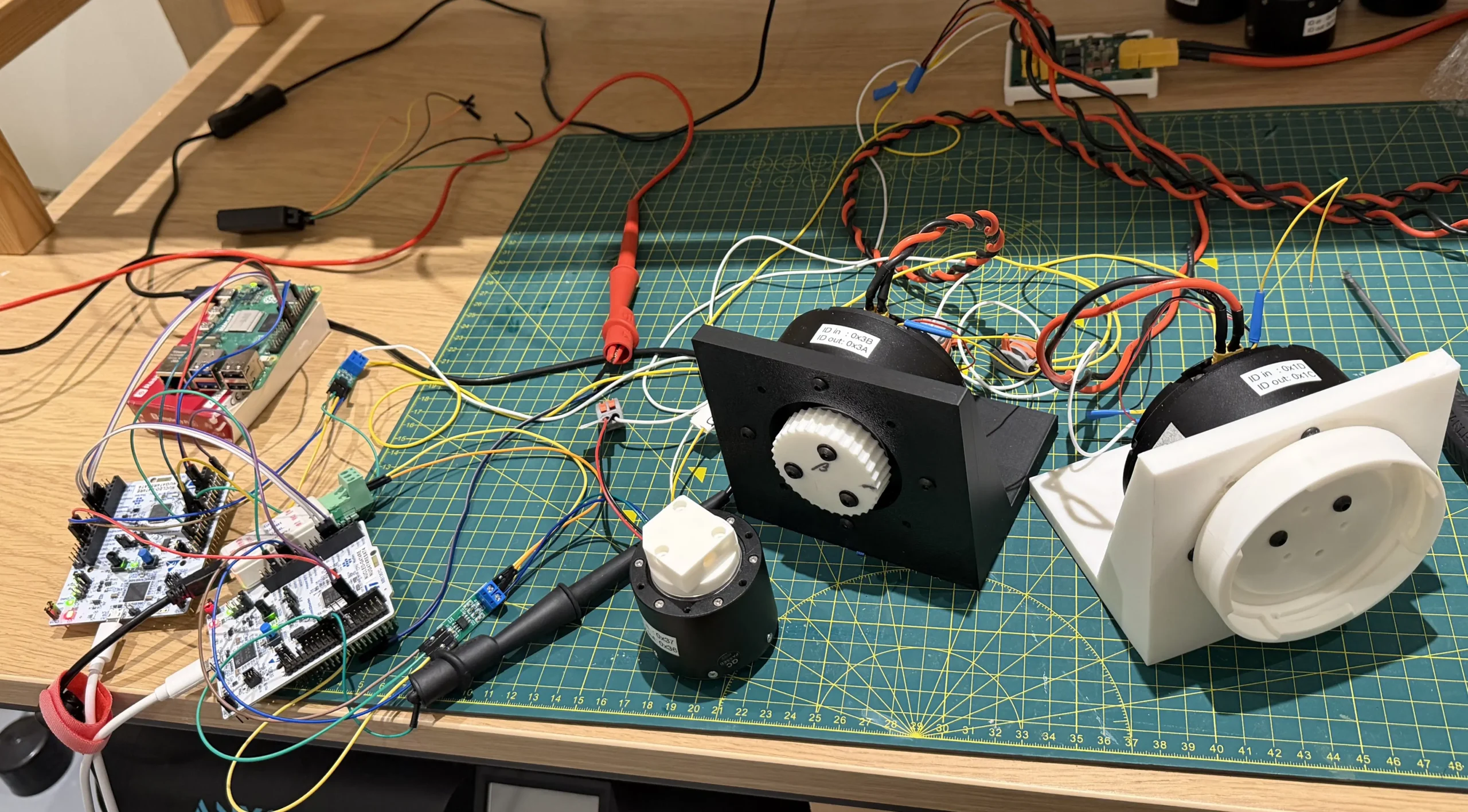
Prototype
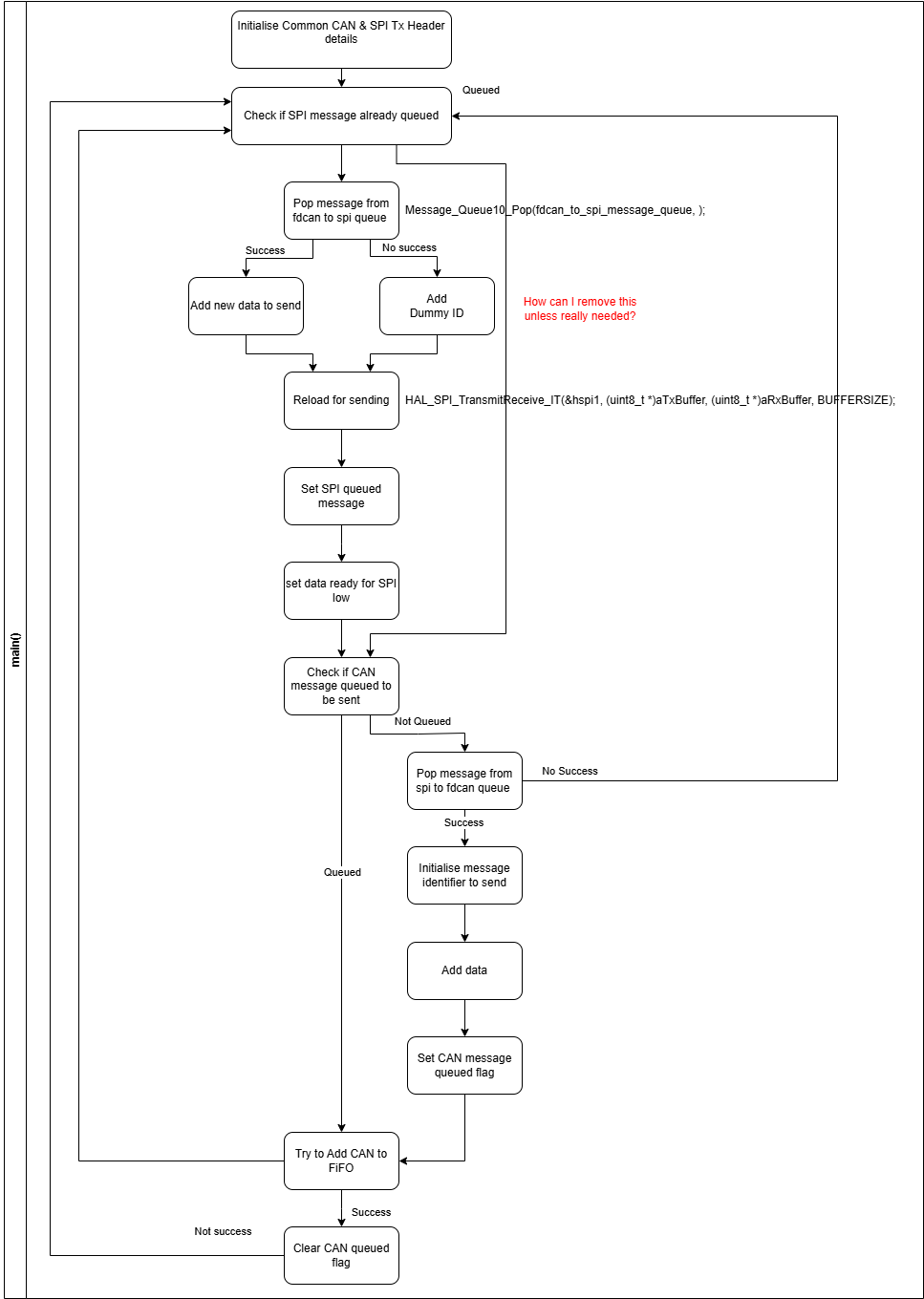
Prototype parts have been ordered (my printer is currently out of action due to house renovations). These cover the left hand lower torso with the key hip joints. Motors have also been ordered. Software is under development to test the motors and joints once the parts arrive.
Shrouding/tidying up
At the moment, there are a lot of open gaps where the hip exits the body. In the future I want to tidy this up, making it both less of an eyesore and also to prevent unwanted items from making their way in.
Motor size reduction
The motors dominate a lot of the space within the torso. If these can be reduced it would reduce the robot’s weight and increase the usable internal space. A reduction of the weight will be helpful for the reliability of the robot’s structure and also the dynamic responses of the robot. With more available internal space can lead to increased options for what can be included inside, speakers, batteries, compute modules etc..
If I can reduce the pitch motor (GIM8115-9) this would allow the yaw and roll motors to move closer to their orthogonal axes.
Easier leg attach and removal
The legs are going to require updates based on what I covered in the leg post. Ideally, I’d include updates to alloy the legs to be attached and removed more easily. A quick release approach could be handy while hopefully not leading to spontaneous robot leg amputations.
For now, I expect that testing “with the leg” may just become the femur inner to reduce the time attaching and removing the rest of the leg assembly.
To Come
Prototype parts of this assembly have arrived and waiting to be assembled.
Another post will cover the build and test of these.
The rest of the Torso design will also be covered in another post.