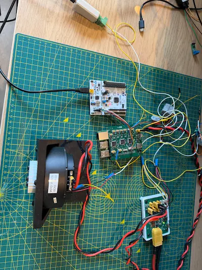
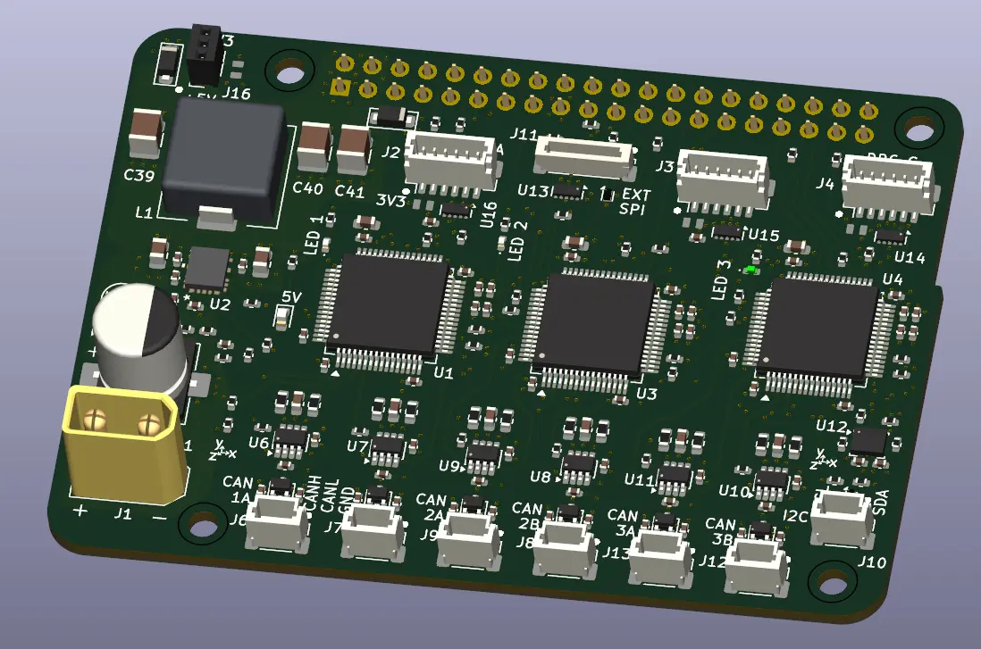
I’ve now got each MCU of the comms board programmed.
The software was built from the latest build in Comms Prototype C.
This made life so much easier to build from. I was largely able to take large chunks of the code with minimal adjustments for the hardware changes.
From the Prototype C build, the main additions are:
- Addition of the battery voltage measurement on MCU A
- Usability of 6 CAN channels
- LED per each MCU
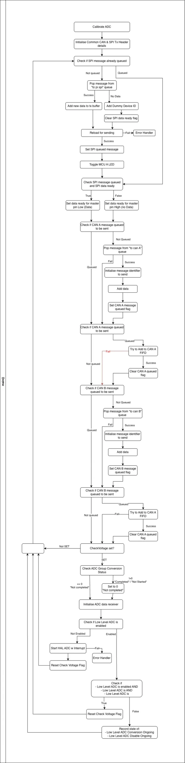
Program operation
A block diagram of MCU A’s main():
A block diagram of MCU A’s ISRs:
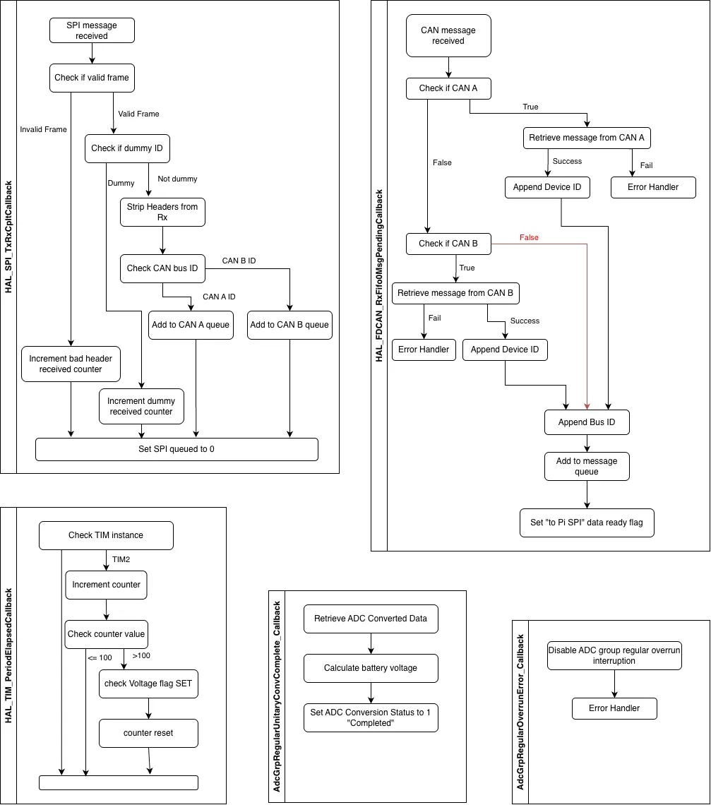
The system operates around message queues to the Pi and to the CAN buses in a single producer single consumer style. As messages are received, the ISR loads them into the relevant queue. To unload the queues, whenever a bus is available the main loop pops a message from the queue and adds it ready to send. For the CAN, these go out almost instantly as the MCU is the controller. For the SPI, the MCU needs to wait until a transfer is initiated by the Pi as it is the master. Data ready flags for each of the MCU are present to help the Pi know that data is waiting.
MCU A measures the battery voltage but doesn’t do anything with it. It may make sense to send this as a “dummy” message instead of a generic info-less “dummy”.
Currently MCUs B and C only differ by not measuring the battery voltage.
For now, all three have their own program, and STM32CubeIDE project, which seems inefficient for the amount of common code. The only common source file so far is the message queue module. I feel like there should be more.
Planned Changes
The other changes that I want to include for “base” functionality are:
MCU A
- UART communication with the Pi
- Shared SPI communication between MCU A, B, and C
- Device temperature measurement
MCU B
- SPI communication with an external SPI device, e.g. wifi module
- SPI communication with A (and C)
MCU C
- IMU running with usable data
- I2C communication with external device
- SPI communication with A (and B)
For the UART and shared SPI bus, I am thinking that this could be used for configuring of the Comms board from the Pi.
There’s nothing really to configure for now, but one I will mull over possibilities as I work through it.
Similarly for the external devices, SPI and I2C; I have a use in mind for the SPI (wifi) but not the I2C.
One change I want to make soon is to up the CAN rate for the motors and the Comms board from 500kbps to 1Mbps.
I don’t have a gauge on what the real bus load is yet, but now with more reliable connections between MCU and CAN transceivers it seems a free win. The testing I did with the CAN bus at 1Mbps in the prototypes worked OK with the dupont connectors and separate CAN modules; I dropped the rate to 500kbps to reduce the risk of chasing errors from the prototype system struggling at the higher bit rate.
Testing and Performance
Currently, I don’t have a quantifiable metric on how well the Comms board is performing. I want to figure out a test that I can determine how well it performs, and where the system bottlenecks are. Once I get a few more motors connected up on the CAN buses I want to understand what the maximum rate I can drive the bus at; knowing the max bus rate will change the control loop rate limits.
Bonus Wins
On a side note, while I was designing the Comm board’s layout I realised that the Pi 4 and 3b had different positions for the USB and ethernet ports. With the spacing I had designed for the 4 I didn’t think I was going to have it be compatible with the 3b; I had hoped to test the Comms board initially with the Pi 3b in case it killed the Pi. With some less than ideal contact between the Pi’s ethernet port and the Comm board’s PCB, it still manages to fit. A small bonus win for development.
Up Next
From the testing since I’ve had the Comms boards, I quickly was limited by the number of harnesses I’d had available.
Both data and power harnesses are limited. The data harnesses are a bit easier to do without as I can roughly join some wires together and not impact things. The power harnesses have higher voltage, and currents that also mostly use the XT connectors, more work is needed to get something ready for use.
Another area I need to look into soon are the motor drivers used. Currently, the Steady Win drivers have been a bit temperamental. I want to understand what the cost and impact would be to switch to another motor driver would be.
Currently, I know the SteadyWin MIT style versions would fit with a cost, harness and software impact. Maybe there are others such as Odrive or Moteus that should be considered, my main concern is the size and shape match.
A more fun area I want to get into soon is implementation of the IMU and getting that data read and shared back through to the Pi.
Leave a Reply