Expanding on from the recent Biped Robot – Hip Assembly Design post, this will give a brief overview of the rest of the torso design.
Architecture
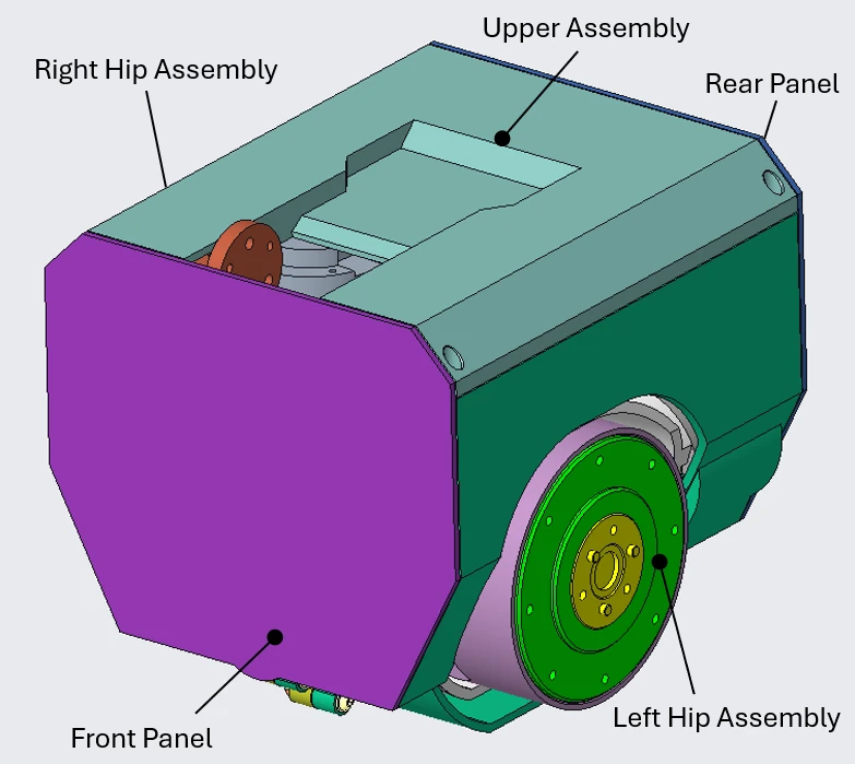
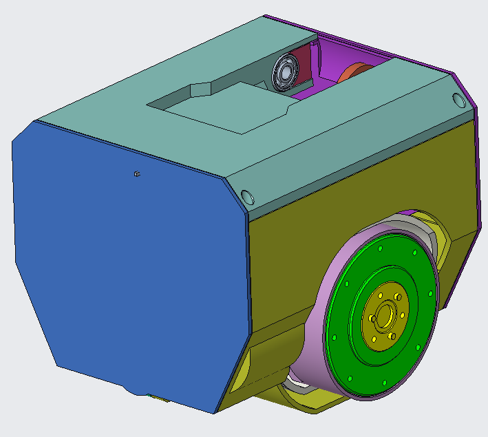
The two hip assemblies provide the majority of the structure and components within the assembly.
The remaining visible from the outside are the upper assembly, and the front and rear panels.
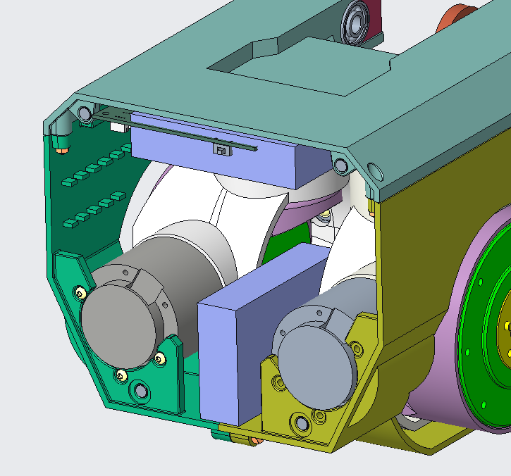
Internally, outside the hip motors and components there is the power distribution board plus space allocated for additional electronics and batteries.
Front and Rear Panels
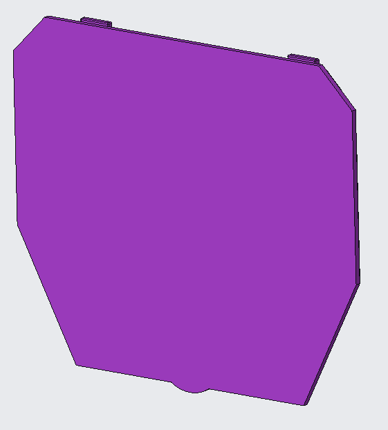
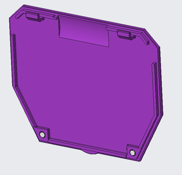
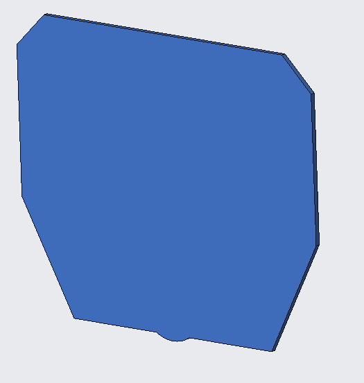
The front and rear panels are currently very basic. Their use is, for now, to simply cover the internals and provide a nicer aesthetic from the outside.
In the future there may be further need to extend their use, such as electronics mounting.
Having an E-switch and LEDs shining through could add to the design from both from a design and function perspective.
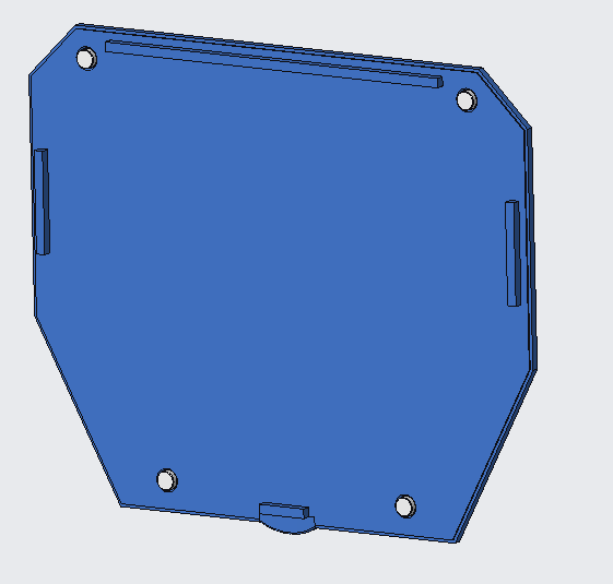
The panels are held on by small magnets, a matching pair being in place on the matching torso pieces. I expect that some tuning for clearances and gaps may be needed to make it feel a bit nicer when using and ensuring it doesn’t fall off through use and inadvertent bumps with the surrounding environment.
The front panel also has two large hooks retaining the top of the panel. I’ll see how these perform and may make the rear or front match the other.
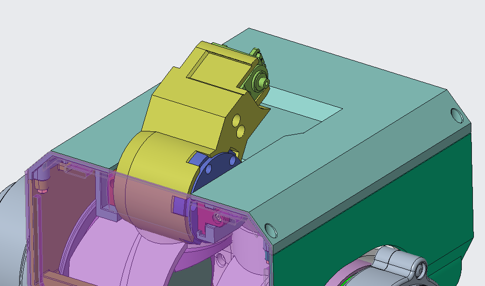
A cut out was needed in the front panel to help shift the neck base motor forward, needed primarily to help with yaw motor clearance.

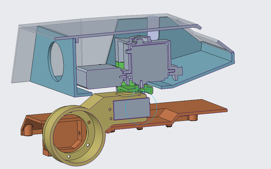
Upper Assembly
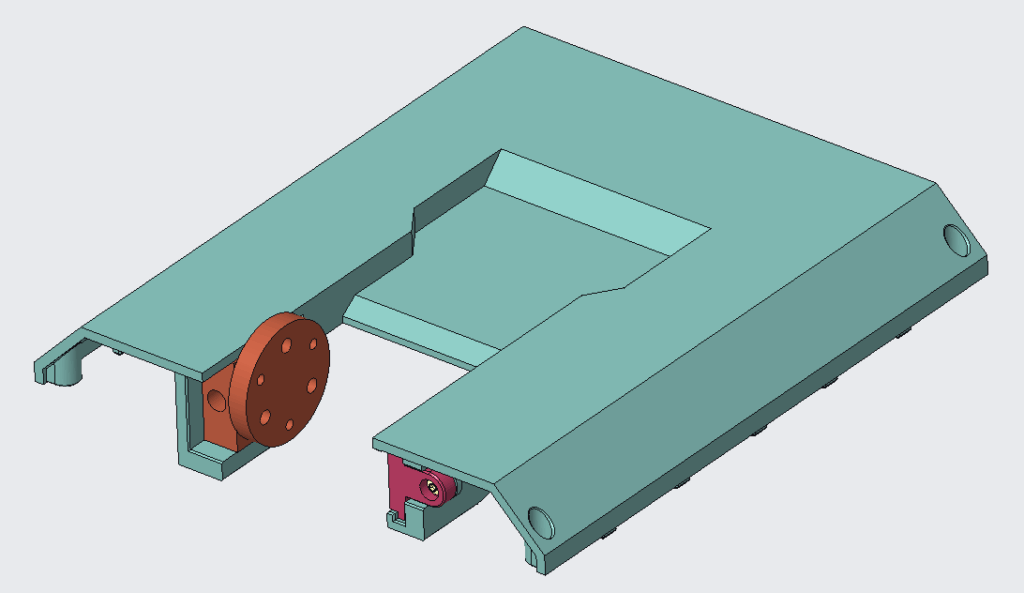
The upper assembly has a few main uses.
- Connecting with the left and right hip assemblies to complete the torso structure
- Provide the mounting and anchor point for the neck base motor
- Provide mounting points for the front and rear panels
- Future versions will have mounting features for electronics
The motor being part of the neck structure was to help provide a neck connection that was strong enough, I believe the strength of the torso will be sufficient or at least easier to strengthen than if the motor mounting structure was done the other way.
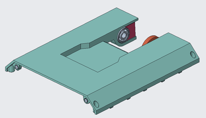
This does mean the wires passing into the neck base motor have to move with the neck, this will definitely need to be monitored on the prototypes.
The cutaway on the upper panel allows for the neck to drop down lower to a somewhat nestled position.
I envisage the neck dropping into here with the head sitting horizontal in it’s power off state.
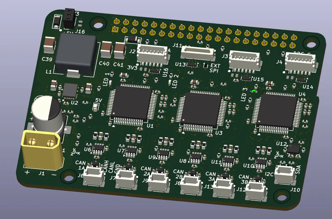
Electronics
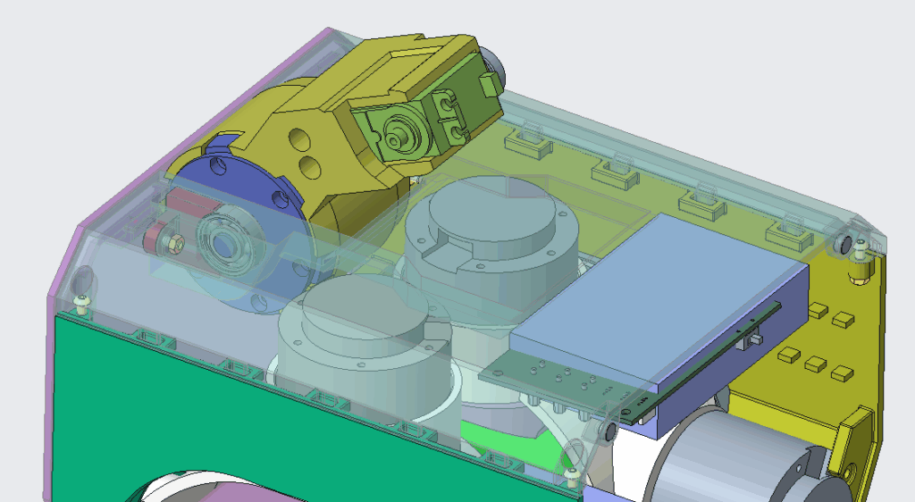
At the time of the CAD being constructed I had no electronics designed so needed to estimate how much space was being taken up and how to potentially attach it. Since then I have created the initial version of the power distribution board, visible near the top of the torso.
The remaining must have electronics are:
- The main control board
- Battery
- Communications module
So far, I have based the main control board around a Raspberry Pi’s volume. I’m hoping that this provides sufficient space for whichever device or approach I take. The NVIDIA Jetson Orin has recently come to my attention but may not fit or be applicable to how I want to control the system.
The battery is my biggest concern for the space, the system has been established around a 6S battery which, depending on the capacity, can be quite large.
Future Exploration
There are a few changes planned already for the assembly but I expect there will be plenty more as prototypes are made and tested.
The biggest top of mind are the assembly between left and right hip assemblies, and the electronics volume and mounting.
The right hip assembly is currently a mirror of the left. The connection between them are through several bolts. To get this connection to a place I’m happy with, I’ll need to break this mirroring and work through a more elegant interface that provides the necessary strength while also being easy to assembly. Definitely want to avoid some of the screw access issues present within the hip assembly.
As I develop the electronics and control system I’ll be able to further refine the mounting methods and battery needs. Ideally I can determine a clever way that gives me flexibility to iterate without needing to reprint the large parts of the torso.