I was keen to get the head design to a more refined state for inclusion in the URDF and planned IsaacLab simulations.
The Head can be somewhat split into the head and the neck with most of the important parts being part of the neck.
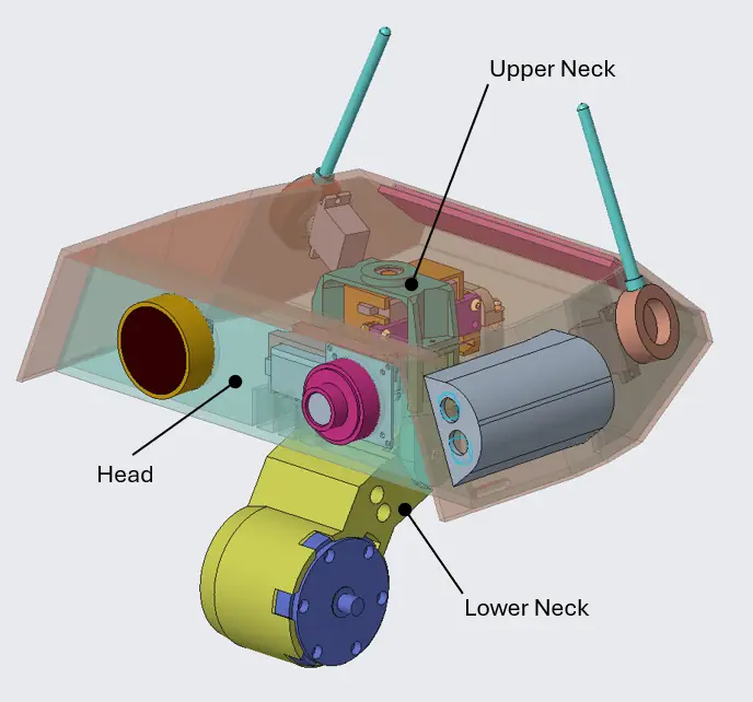
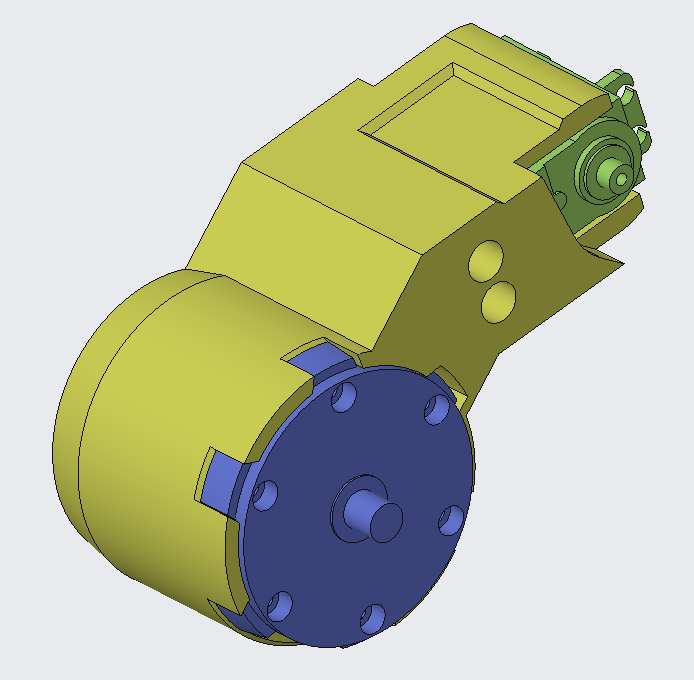
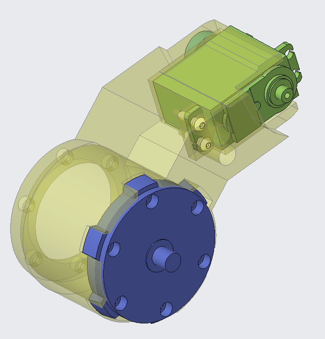
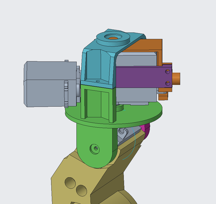
The Lower Neck
The neck interfaces with the upper part of the torso where the neck motor is mounted, and extends upwards housing the head pitch axis servo.
As the wiring becomes more refined, I’ll need to add accommodations for this too.
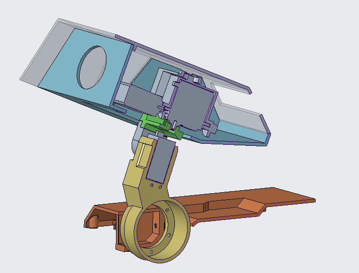
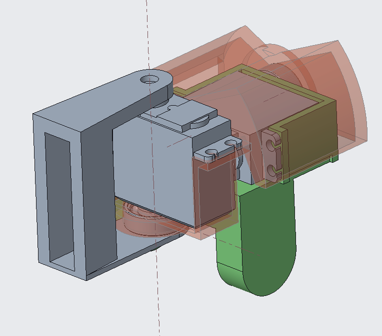
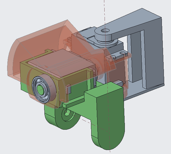
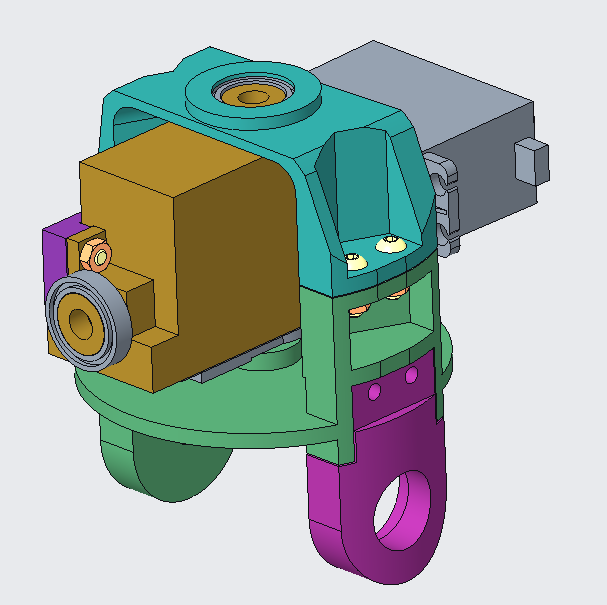
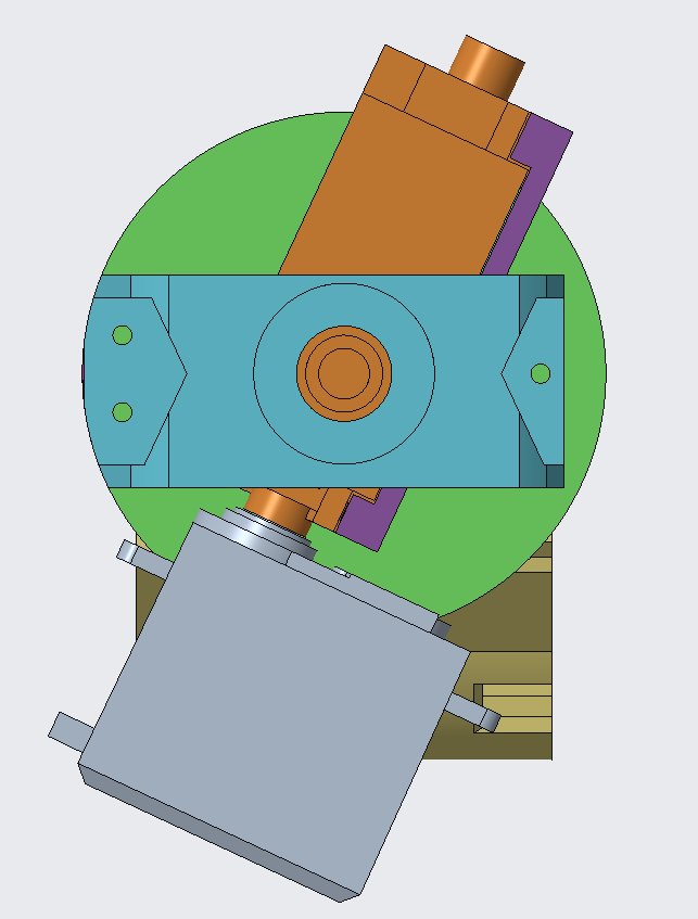
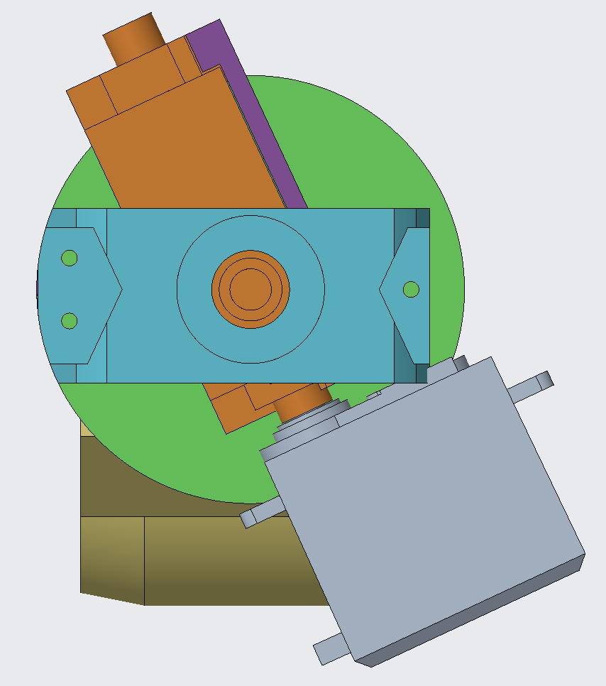
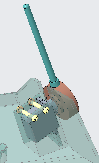
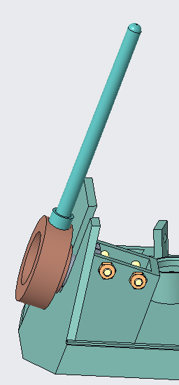
The Upper Neck
The upper neck provides the connection between the lower neck and head whilst providing yaw and roll axes to the head and the second side of the head’s pitch axes.
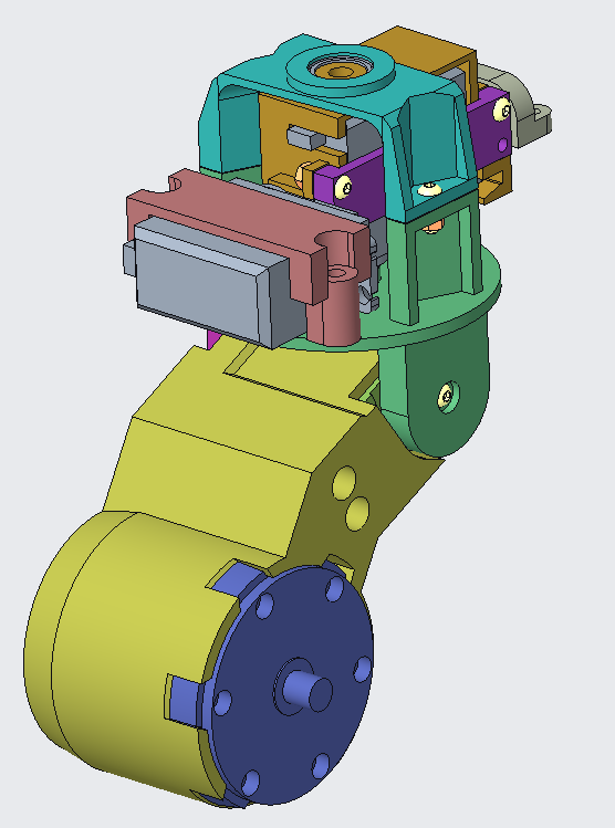
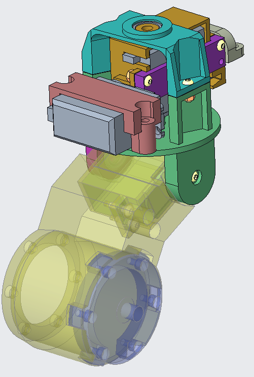
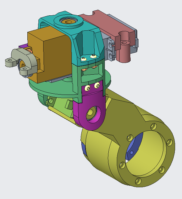
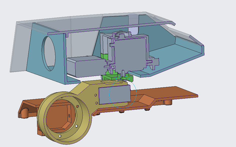
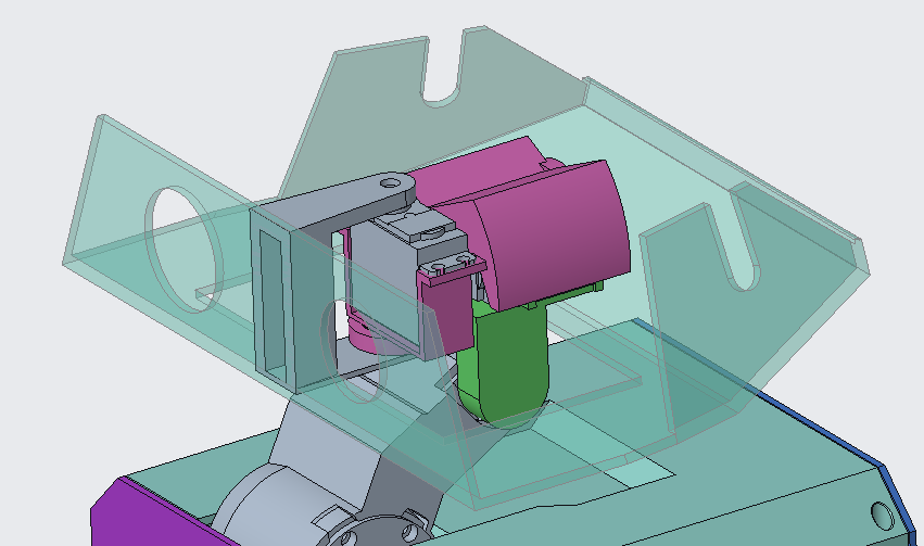
The primary challenge was defining the order of pitch-yaw-roll for the head that could fit within the desired head volume and robot’s height.
I started the exploration with sketches but the challenge became more apparent when trying to implement it in CAD. The size of the servos and the small size of the head skeleton quickly highlighted a disconnect.
To settle on an upper neck design, multiple rounds of iteration were needed on:
- Head height,
- Robot height
- Pitch, yaw, and roll axes position
- Bearings
- Interconnecting structures
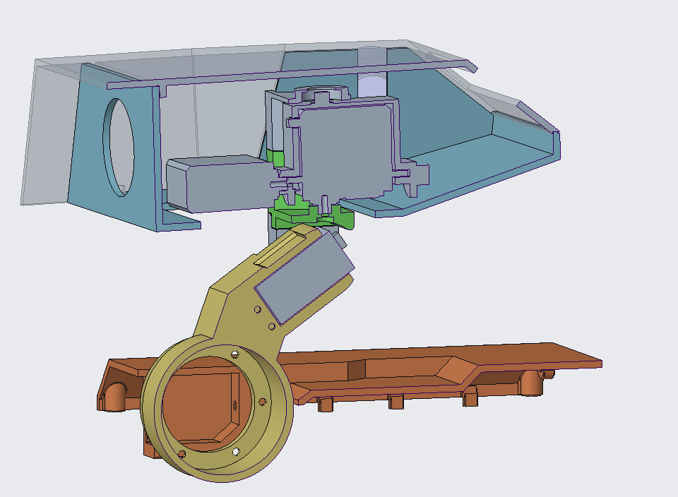
Initially, I had Pitch-Roll-Yaw (P-R-Y) as the lead path but this had a large issue with the carriage and head underside worked together. It also had a large distance between the top of the lower neck/pitch axis and the yaw axis which I wasn’t happy with. It did, however, have a lower height within the robot head, albeit in early CAD.
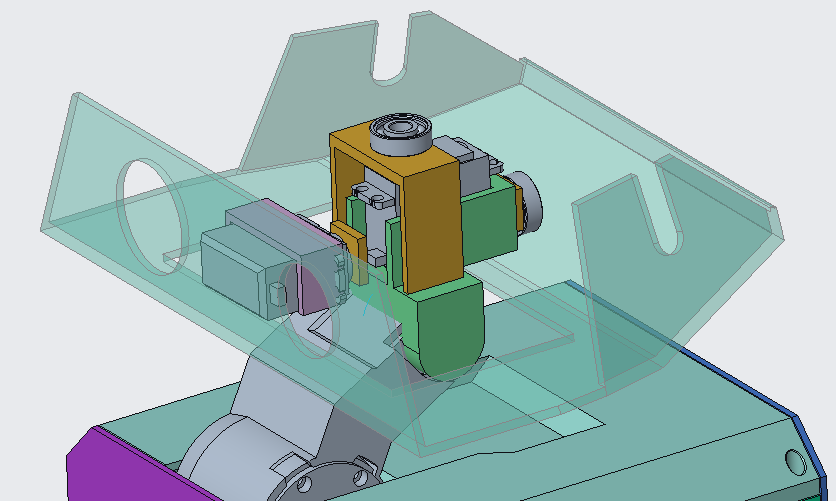
Additional, parallel CAD was added for the Pitch-Yaw-Roll design.
This lead to doubles of almost everything from the torso up using additional axes. The height of the head and also the robot did increase a bit but the head growth was largely gained by lowering the head’s bottom surface.
The P-Y-R order allowed for the Yaw and Pitch axes to be quite close. The interface between upper neck and head bottom surface was also left to be a simple circle.
Smaller bearings (than used in the legs and torso) were incorporated to minimise the increase in the robot’s head’s height.
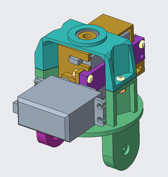
All the non-purchased parts are intended to be printed in PLA. Similar to the lower neck, wiring needs to be accommodated into the design as the EE system gets built out.
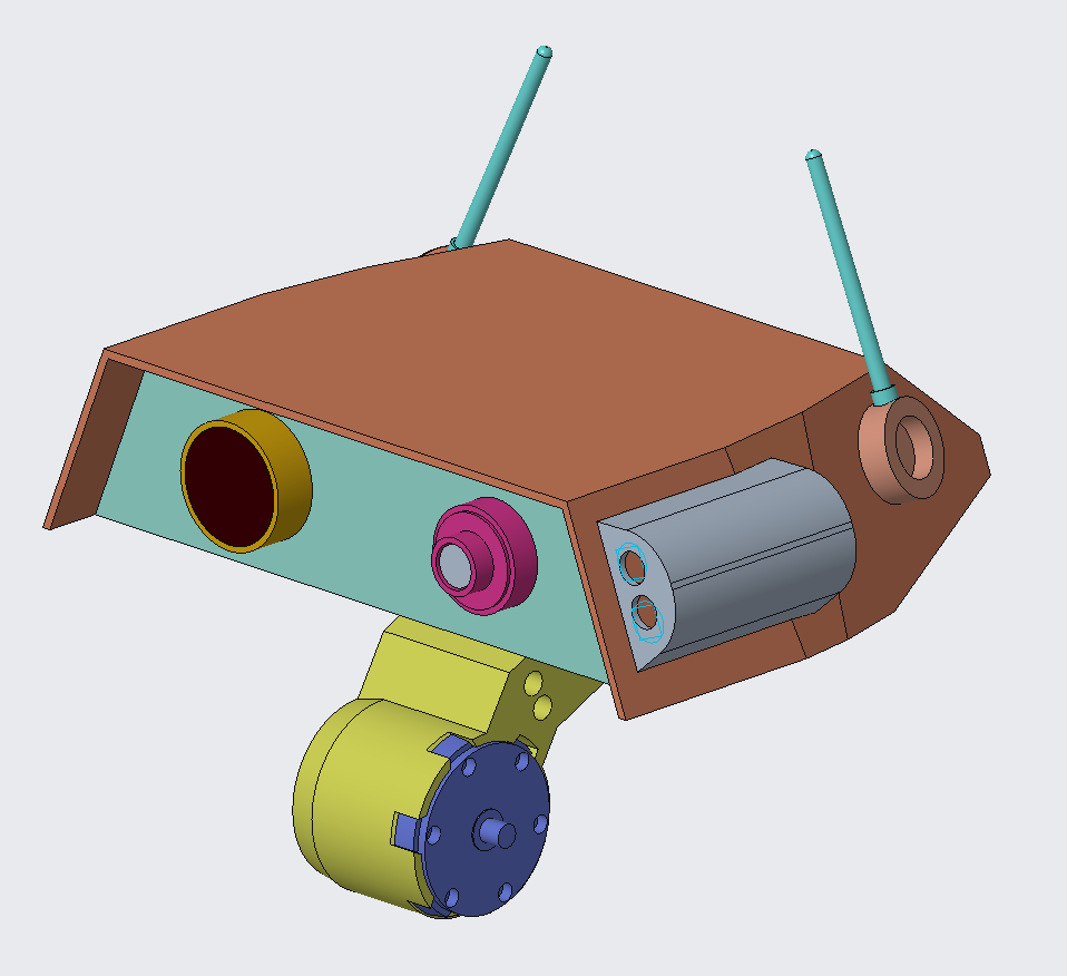
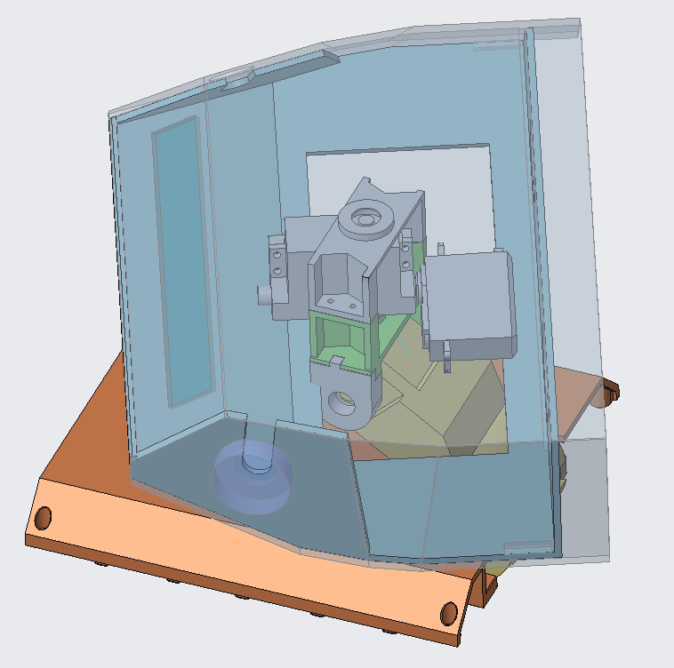
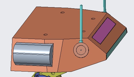
The Head
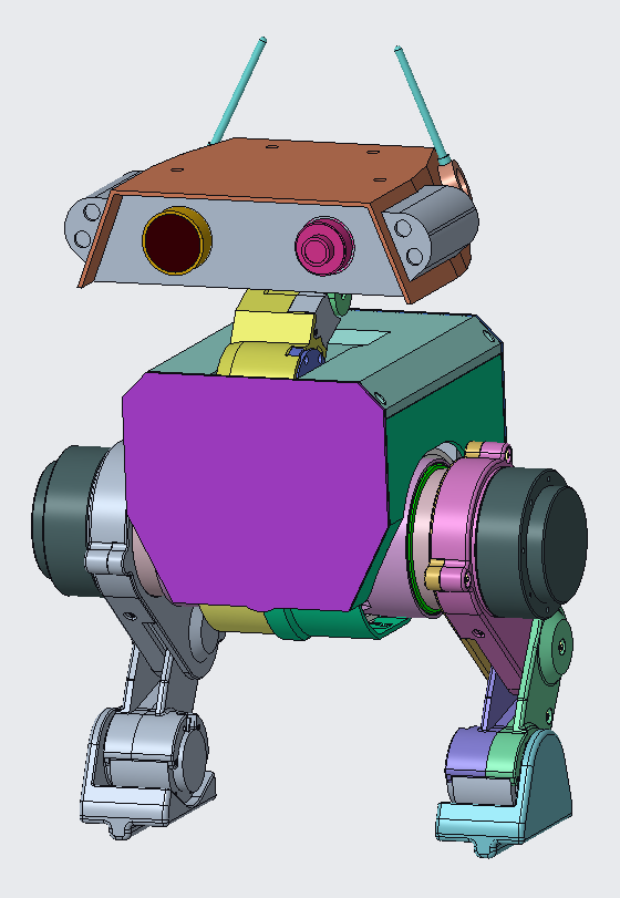
The head design is currently cosmetic with intended flexibility to allow added functions later.
At the rear there are two “ear” antennae. To help provide an additional avenue for the robot to express “personality”, whether that’s remote controller or otherwise. These are to be driven through two small hobby RC servos.
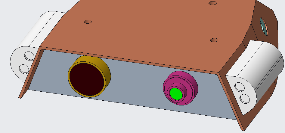
At the front there are two “eyes” and two torches.
At some point I want to include real cameras and expand into using computer vision to supplement the control and behaviour software. I roughly sized out some lens place holders (primarily aesthetics) and some space for camera modules I encountered online (a raspberry pi camera and a xxx camera). This was to ensure sufficient space was kept at least for some basic options.
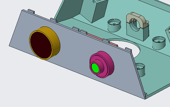
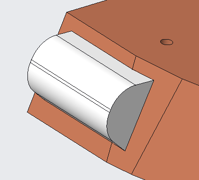
The torches are also Sci-fi inspired, the housings are ideally going to be hot swappable allowing for different combinations and uses. To begin, I’ll likely use some white and maybe coloured LED’s. It would be cool for future versions to incorporate other types like IR that could add extra functionality by itself (like TV control) or with the cameras and improve their usability.
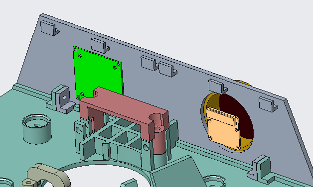
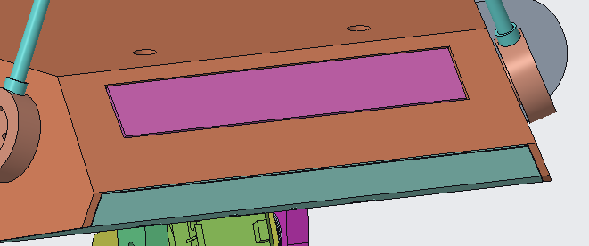
The rear panel has been space saved for an LED dot matrix panel. Partially for the added personality, some Sci-fi style and early on for debugging and providing feedback while under development. No specific module or board was used to design around so I expect this to heavily change.
No definitive space has been allocated to speakers or compute modules in the area with the latter possibly creating some issues with spacing.
Future Exploration
The most important next step is to build a prototype of the neck and head to verify the fit of parts and the capability of the servos to deliver what I am aiming for. Assuming it all works, it will also be worth including tests with some additional weight added to the head to simulate additional internals such as the LED panel, cameras and other electronics. This will help me to understand what margin I have or need to be concerned about.
Beyond that, the other areas are those that I’ve mentioned:
- LED dot matrix panel on the rear of the head
- Torch/light modules on the side of the head
- Camera and lenses
- Speakers
- Any electronics to control
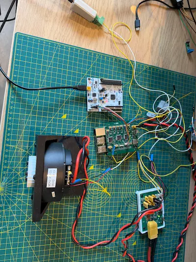
The prototype and internals will need some basic electronics to enable the use of for initial tests.
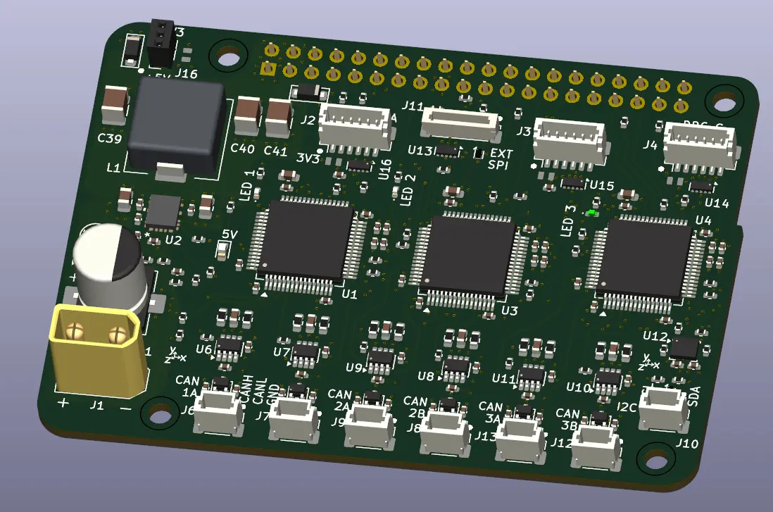
- CAN driven control for the lower neck base motor (can leverage work done for the hip motors)
- Servo controllers for:
- 3x MG996R servos for Pitch, Yaw, and Roll Motors
- 2x Longrunner servos for the “Ear” antennae
To print the design on my FDM printer (Anycubic 4Max Pro), I will need to further split the head upper and lower pieces to fit the printable area.
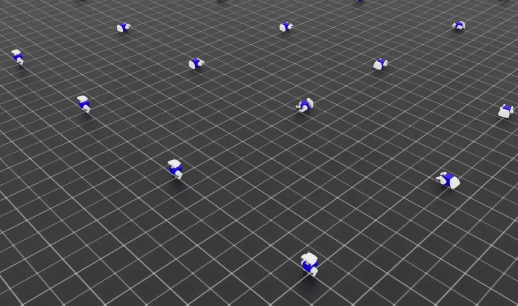
Outside of the head and neck, the CAD, and calculations of mass and inertias will feed into the model used in IsaacLab simulations.