To further expand the number of motors being powered at one time, and eventually using batteries, I needed a board that could provide the outputs and also manage the inrush current with the motors connected to prevent damage of the motor controllers.
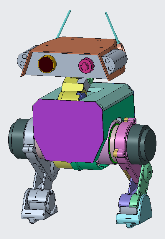
Development of the hip sub assembly prototype requires 3 motors to be powered for the hip and a fourth to add in the knee for full left hand side hip and leg.
The larger 8115 motors require minimal current with no load but this can exceed 5A when faced with a resisting torque.
The smaller 4310 motors have so far operated below 500mA with load.
The full system with all actuators and control system requires a not insignificant current (if using the data sheet nominals plus some buffer) of ~50A.
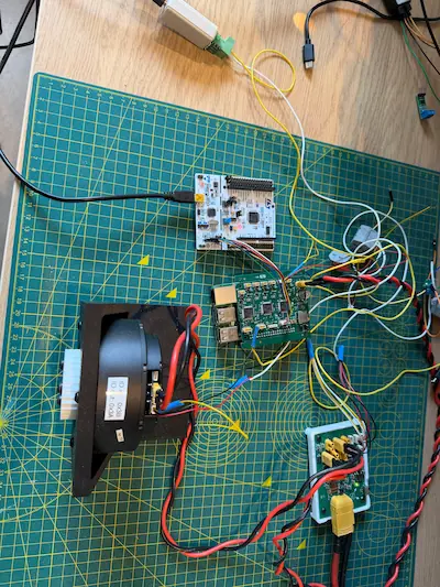
The power supply I have (an RS-D3305P) can provide 5A for each the 2 primary channels, or 10A for a single channel.
So far it has allowed the hip assembly to be run with the 4310s running from one, and an 8115 from the other with no major loads being used.
To add the knee motor I want to initially set up all to run on one channel with 10A, and eventually switch this over to a battery.
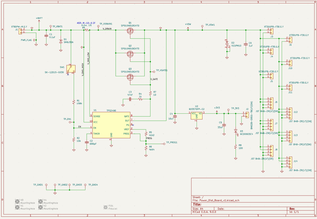
Design and Schematic
The board design focuses around a Hot Swap Controller, TI’s TPS2490, which was available on JLCPCB and also came with clear documentation and a calculator to guide component selection. TI had several other options like the LM5069 and Analog devices had the LTC4260, I chose the TPS2490 over these primarily on the cost and it being simpler with less features (maybe for a future version).
The remaining components on the board are the 3 MOSFETs that the TPS2490 switches, input and output connectors, a 3.3V LDO, status LED, power switch, a TVS diode and a freewheeling diode for when the power is disconnected.
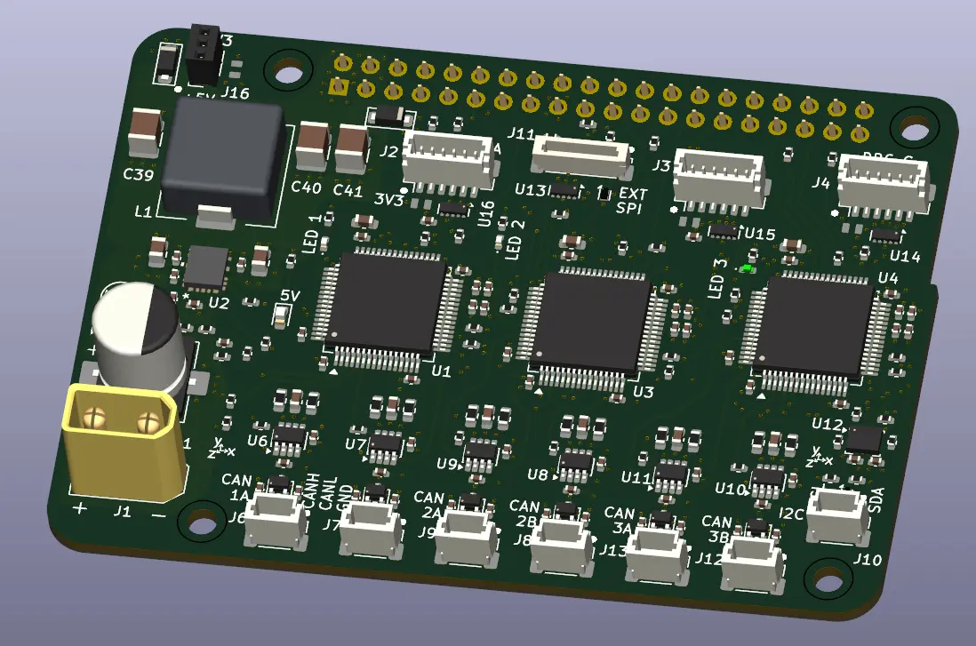
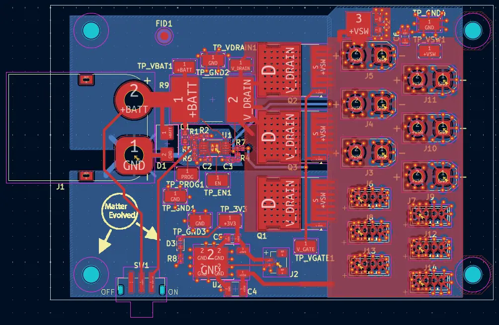
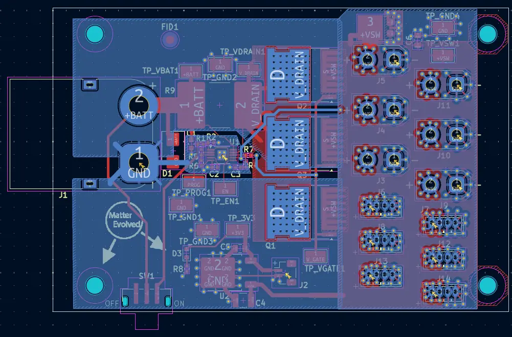
Layout
My aim in the layout was largely on trying to minimise the current heat loss by minimising length for the power to travel, and maximise the area for it to travel. This performance is something I’ll definitely need to understand with the initially ordered prototypes, and hopefully in the meantime learn how to run some thermal analysis simulations to help future designs and versions.
The other aspect I tried to achieve was lots of area for the current return paths.
The board stack up is 2 layers of copper, 2oz, with 1.6mm FR4 core.
Components
Component selection was initially done through LCSC, as I planned to get PCBAs from JLCPCB. I learnt that not all LCSC stocks are available at JLCPCB so some rework to schematic and layout was needed but thankfully not too much.
Initially I had a buck converter to provide the 3.3V, enabled by the PG pin on the TPS2490. This wasn’t available and became an LDO.
Using a device that can be enabled with the PG pin is preferred as it allows for less load on startup. I am not expecting the LDO (and it’s downstream demands) to require much versus the motors so this should be ok.
Final design
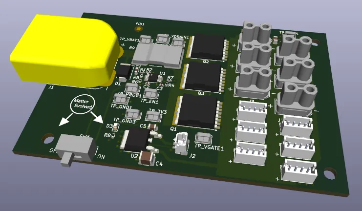
The boards with assembled components have been ordered from JLCPCB, will share updates on how they perform.
The design does need further time to finalise where it’s going into the torso. It came out larger than I was expecting so may need further refinements to balance position, size, and mounting points.