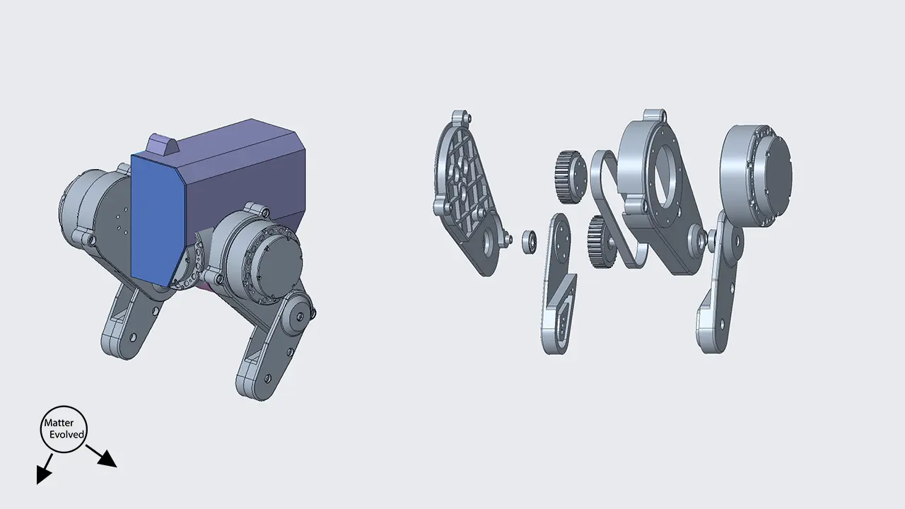
Going from the basic leg position layout used in the dynamic model, and with a motor selected I could further solidify the design of the robot’s leg.
CAD Walk-through and Prototype Demos
Main Structure
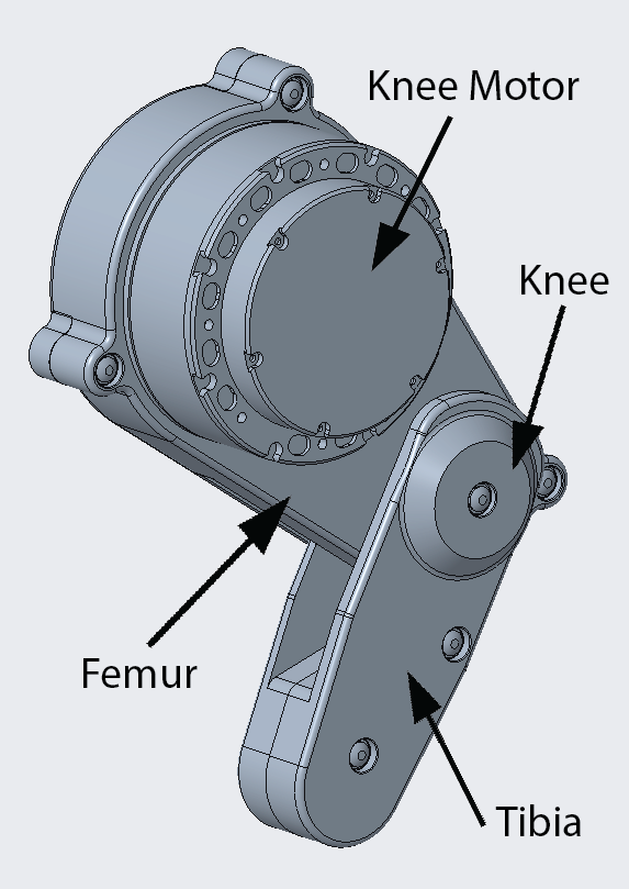
The overarching structure is straightforward with the leg comprised of a tibia and femur and two motors (hip motor not shown).
Apart from the motors and hardware (nuts and bolts, bearings, and belt), all parts are FDM printed in PLA.
Originally, the intent was to have a foot located the could rotate around the end of the tibia. I decided to eliminate this aspect of the design to simplify the overall design, I intend to bring this back in the design at a later stage.
One the early decisions was knee motor placement. From the designs I have seen, there are plenty that have the knee motor coaxial to the hip motor/axis and plenty in the knee location. One of the main drivers to have the knee located on the hip axis is to reduce the moment of inertia that the hip motor needs to overcome when trying to move the leg. While this is still a problem in the biped, the significance is a lot less compared to a quadruped due to the much lower leg and rotation velocities (as my current design intent stands at least). The other influencing factor was simply the size of the motors versus the leg. If I was to place the motor at the knee the size of the motor dominates any structure or form.
Knowing now that the motors are bigger than needed, I can re-assess if a smaller would function in the knee axis.
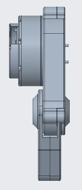
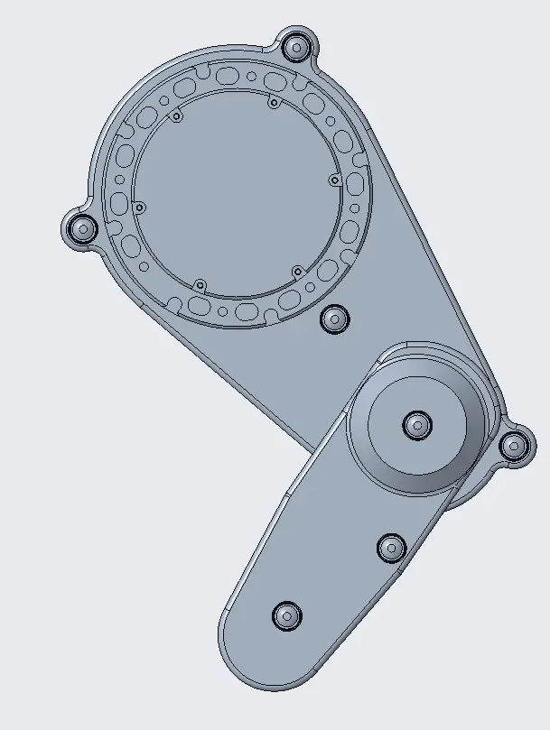
Placing the knee motor at the hip does add additional problems, primarily, the issue of transmitting power from one axis to the next. More covered on this below.
Femur
The femur assembly consists of the knee motor (hip motor is part of the torso assembly), the power transmission assembly, and the femur shells.
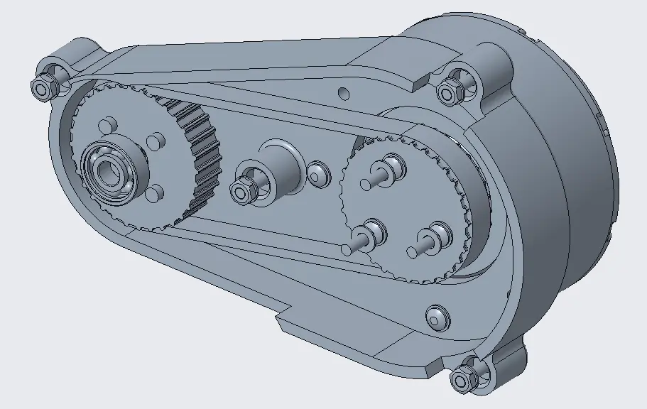
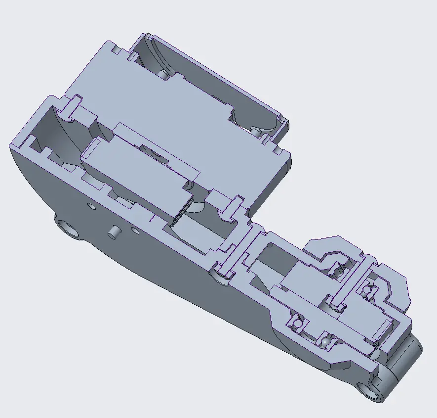
The femur shells are two large pieces that provide the leg aesthetic form, provide mounts for the motors, and clamp the knee parts together.
Power Transmission
The power transmission uses a timing belt with two equally sized pulleys, the upper is mounted direct to the knee motor, the lower is housed with bearings being supported by the femur and tibia pieces.
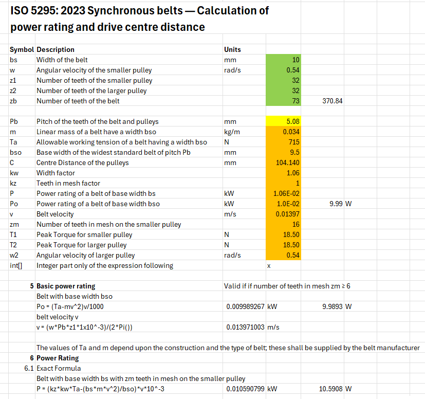
Specifying the belt and pulleys relied on the power and torque requirements from the dynamic model and calculations from ISO-5295, which I turned into an excel calculator. I found a belt and pulley supplier and used their data sheets to iterate through different belt and pulley sizes, diameter and width, until I met the requirements. I aimed to limit how large the diameters would get to avoid growing the leg size. The centre to centre distance was adjusted until it approximated the existing design.
The chosen belt was from the Optibelt Alpha Power Range with the pulleys matched to this profile.
Unfortunately, when I ordered these parts (from a local supplier) I received Alpha Torque belts which didn’t have the same level of performance. The initial prototype build included this Alpha Torque belt which will be replaced with the Alpha Power (replacements were sent) once I rebuild it.
The design doesn’t have a tensioner which will likely need to be added to help maintain reliable engagement between belt and pulley, and also simplify assembly.
Knee
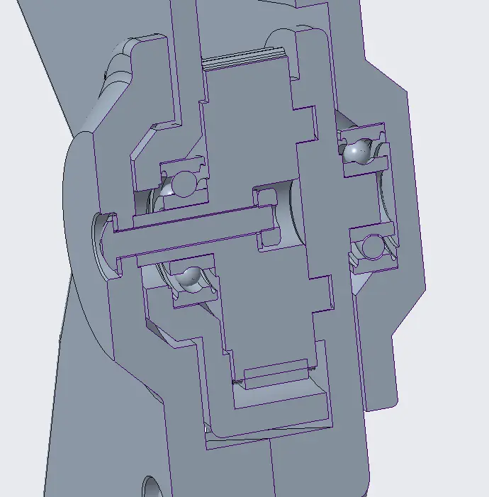
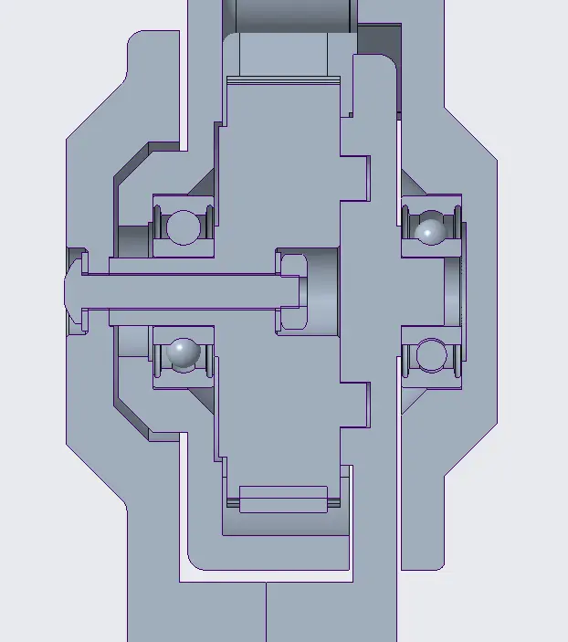
The knee has the pulley in the middle.
On the outer side (left in images), this is supported by an SKF608 bearing. The bearing ID is 8mm, which I felt was big enough that the post from the pulley would not fail quickly under load. The pulley may need to change material once under regular use.
The bearing is held in a pocket on the femur outer part. The tibia in turn, encapsulates the joint helping to clamp these together.
On the inner side (right in images), the pulley engages through four pins to the tibia inner part. The tibia inner piece is supported by another SKF608 bearing held within the femur inner part.
To allow for transmission from the pulley to the tibia without small parts, the geometry has resulted in an overlapping structure with the tibia and femur each having one side within the other’s walls.
Tibia
The tibia consists of two halves which clamped together provide a foot and house the knee power transmission pulley and interfaces. Adding in more hip range of motion (beyond forwards and back) I’ll likely have to round the base of the tibia along the coronal plan to minimise weird behaviour from encountering corners.
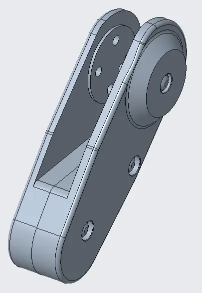
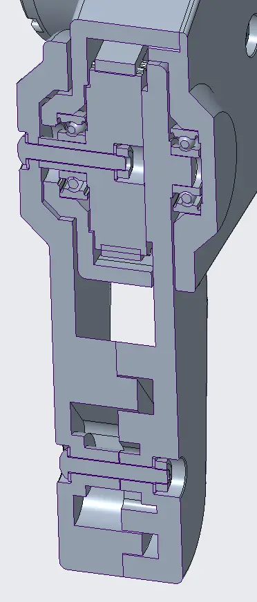
Motion Envelopes
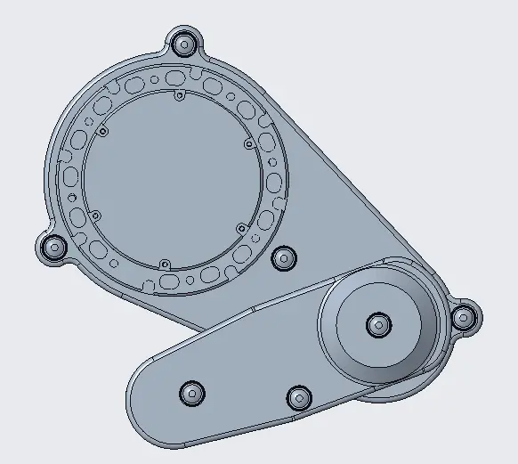
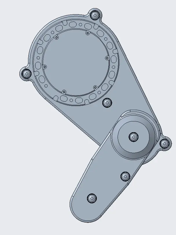
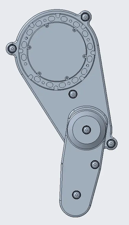
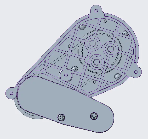
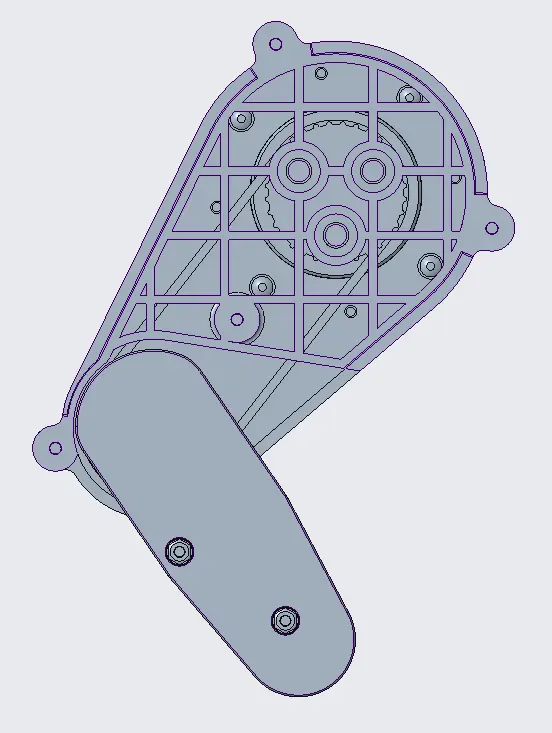
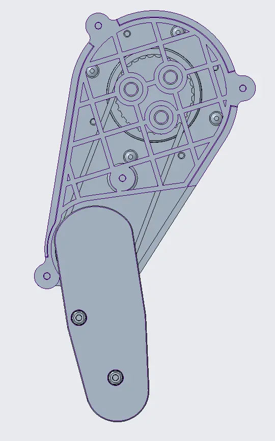
To allow for the range to squat and stand, due to the overlapping structure open space was needed in both femur and tibia to avoid clashes.
In the lower squat position, the robot is also able to use the foot end of the tibia and the knee end of the femur as a stable four point way to sit and power off.
Prototype
Joint Motion Logging Demo
This demo was used to help build my library for communicating and retrieving information from the motors. It also enabled me to confirm that the belts and pulley were moving and operating as intended.
To see the video jump to 08:03 of the youtube video.
Driving Demo
This demo was used to further expand the motor library for driving but mainly to get a hang of controlling these motors. I was super worried about them trying to over rotate into the hard stops (I opted for no limit switches or detection) so built it step by step. The movement behaviour in terms of oscillations is quite inconsistent from run to run and also motor to motor. I want to migrate over to controlling them from an embedded evaluation board to try and limit potential influences to fine tune the control algorithms behaviour.
To see the video jump to 08:49 of the youtube video.
Disassembly
To see the video jump to 09:24 of the youtube video.
Main learnings from the disassembly were:
- The belt became much more slack than when installed
- The knee pulley had loosened off
The knee pulley loosening can be easily solved with an adhesive or meshing geometry.
The belt loosening has a few potential root causes between the belt and pulley which will change the needed solution. More investigation is needed.

